I guess I was fooled by wishful thinking and images like the one below.
It is a 3D object, but it is made from straight lines.
Making concaves will be a bit of a problem with that method…
.
Anyway, I think the UTFB might be an option. Straight lines and convexities only, easy-peasy!
But a 2D file will not cut it, still.
How about 3D routers?
The one in this video could do one side of a fin, but doing the other side could be a challenge: https://www.youtube.com/watch?v=dcKq08oLQBw
Skip through it in chunks, it is a bit drawn out…
MrMik, 3D routing is ideal for making fins and moulds. It is faster than 3D printing and opens up different material sets.
I hope you get a chance to mould some of your proven favorite designs.
Scroll through the Twitter for finfoil to see some of the fin-related stuff that has been done.
3-axis CNC routers are great!
I have one in my garage and use it to cut fins.
My experimental finfoil code is already generating CNC toolpaths for 3-axis routers.
This method is great for one-off prototypes, but still quite labor intensive.
Creating molds from the CNCed halfs currently seems the best option for small batch production.
Aha, looks like I spotted the main problem at first sight: The second half cannot easily be created by CNC routing, need to glue them together. Quite simple, by comparison.
.
ebay throws up a bewildering and surprisingly cheap array of 3-axis CNC router on first search.
The method looks like a mirror image of 3D printing and should be relatively simple, except for all the toxic dust and the difficulties routing the underside of the object. And the regrettable waste of material, just what stopped me from ever sanding back my first lamination for a wooden fin making attempt. But now, I have a 3D fin design that is worth creating some dust for.
.
I shall google 'How to choose a 3-axis CNC router"…
Actually you can do both halves in one piece.
It requires you to mill alignment pins in your wasteboard and stock material.
This allows you to flip the material over in close tolerance.
This is on the roadmap for future enhancements to my code.
But I currently don’t need it so I’m focusing on other things.
I had access to a 3 axis CNC but the problem was that I had to redraw fins myself to get a proper parasolid model I can generate a toolpath from with Fusion360.
I’ve learnt how to draw a fin now but it’s just a basic NACA foil and a high aspect ratio profile - no lovely bumps.
My workshop has closed at the moment. When it reopens I’ll try to cut that fin out. I’ll be gluing 2 halves together though.
I tried gluing 2 3D printed FCS tab halves together - couldn’t get the thinner section to print properly on the bed… probably need to make it thicker and use a heated bed.
Tried out the HTUB (non gullwhale) again. Once again, waves poor but I really liked it in the forward position on the 6’6" pin so really it was not a fluke. It’s my favourite setup now
Mik, if you have any toolpaths you’d like me to try, even just testing non fin ideas out, just post em up and
hopefully I’ll have a go when the workshop reopens next month
Currently finfoil’s toolpath generation is not publicly available.
But just send me a request with a foil file and your machine and material parameters and I’ll generate a path for you
I use my 3D router like most people use their 3D printers…and do not need a parametric model for each project.
I have another mesh-based CAM program that allows me to make 3D code for any STL file, 2.5D for any DXF (x,y with a fixed thickness z), and relief carve various bitmaps where shades of gray equal cutting height.
It works great for at-home projects-anything surf related that fits on the machine including fins.
On larger objects one can see the faceting induced by the STL format, and that is when a solid modeler and better CAM software would shine.
We just got a CNC mill at work so I am hoping we get some industry grade software.
The CNC stuff in Fusion360 is pretty good too, some of its algorithms are better that my other mesh-based software.
I still think finFoil is the fastest way from thought to fin. With the G-code option it can work with both additive and subtractive processes.
The current g-code generation I developed is specific to 3-axis CNC mills.
But I guess that you mean that the current STL files are already sufficient for additive manufacturing?
There are no plans to generate 3D printing g-code as slicing software for 3D printing is already close to optimal for 3d printing fins, while for substractive manufacturing there is much room for improvement.
Yes, I think the current STL files are a great starting place unless you are in need of something specific (highest resolution or additional components like fin bases, etc).
Go finFoil!
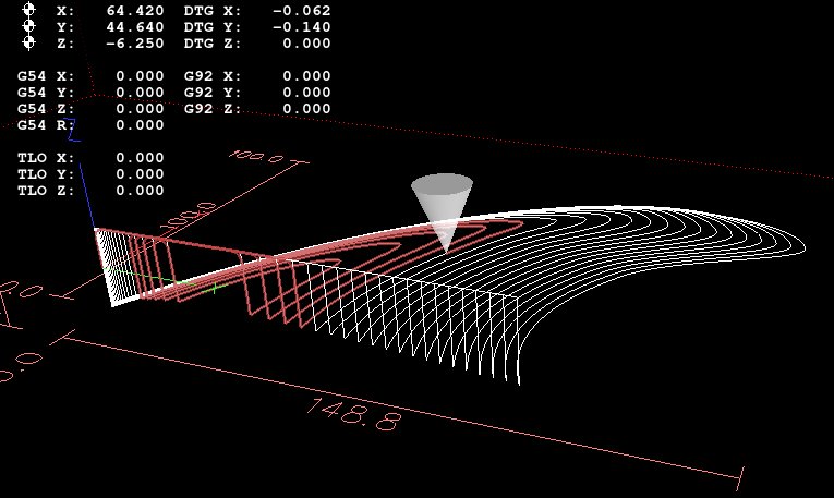
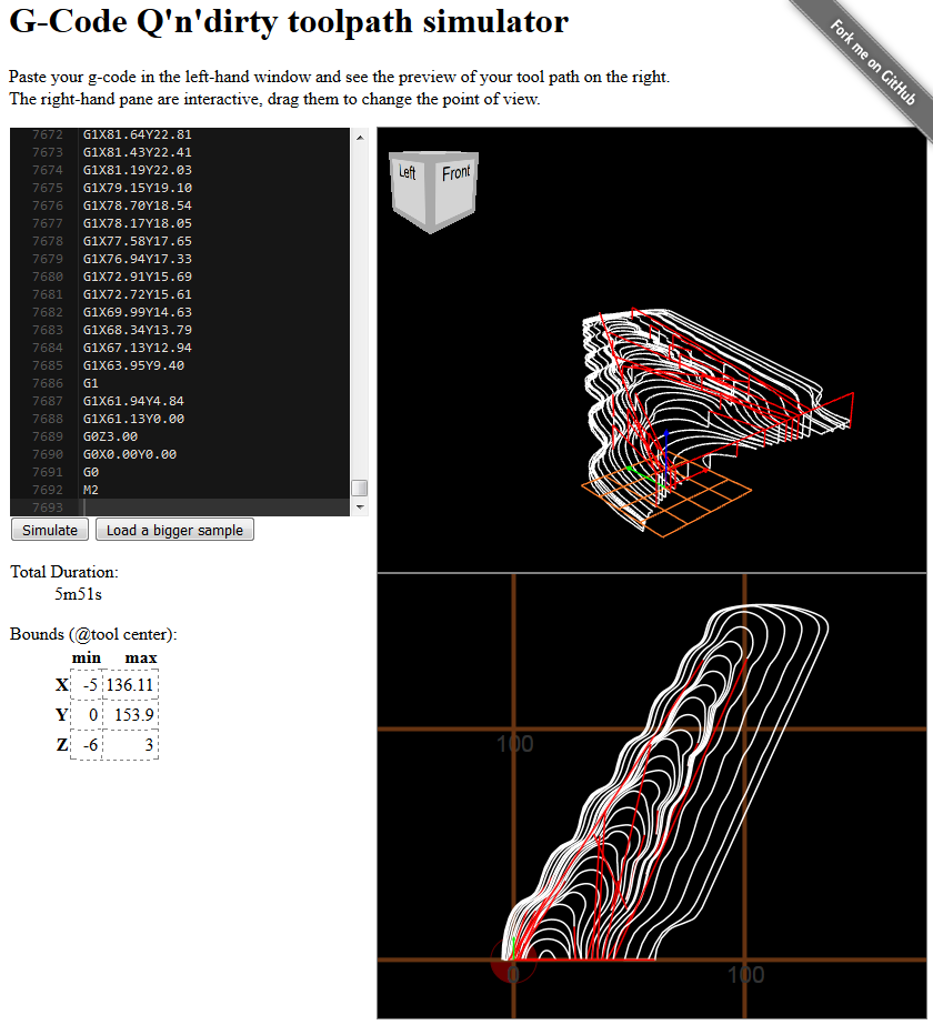
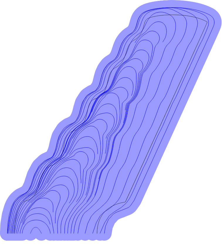
To illustrate the great thing about CNC routing with finfoil toolpaths, I applied it to one of your fins.
The image below simulates the finfoil generated toolpaths with real machine parameters I use on my hobby type CNC machine, industrial machines can go faster.
The machine time is only 5m51s!
The image below shows the toolpath top view (dark blue lines) and tool coverage (light blue areas).
The outline is also plotted as a thin black line:
Wow!
The same fin, 3D printed with lots of infill for resin soak method, took 21h11min to print (including fin tab, but also including a lot of support material that needs to be whittled off manually)
Clearly an advantage for the CNC machine.
What material can you cut at that speed? And how good is the surface, does it need sanding or further treatment after routing?
I have looked at a few options, but I want one that I can adapt for wet routing. Too much dust otherwise.
The only thing I could find about it so far is this video with a defunct ebay link: https://www.youtube.com/watch?v=IXPO0iEZGOY
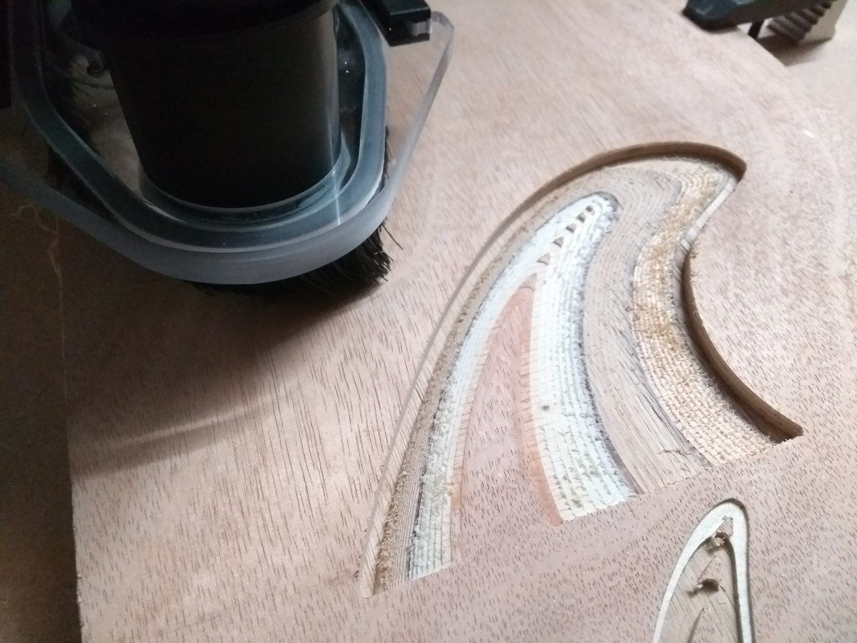
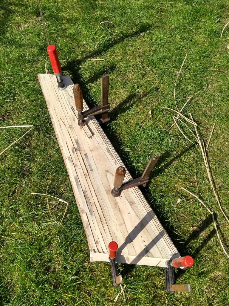
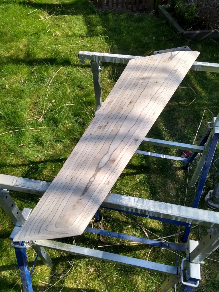
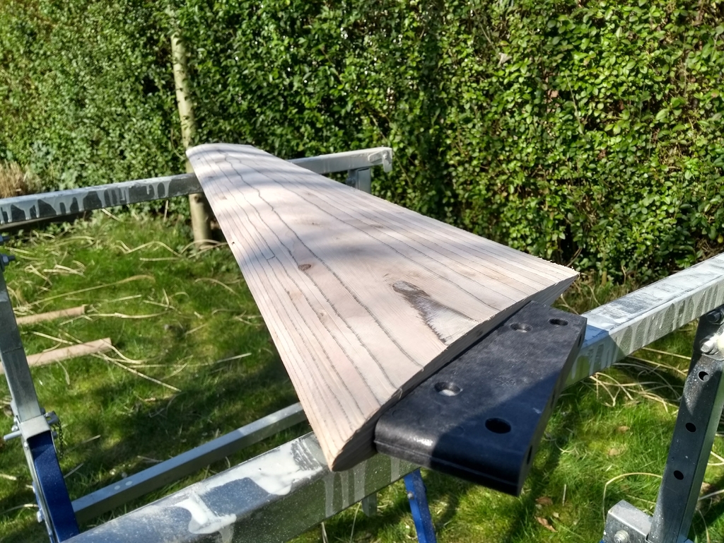
This is toolpath is for cutting plywood with a 1cm flat head router bit.
The result is a stepped profile that needs finishing with a small plane, a round spokeshave for concave parts and a sander to sand smooth.
This finishing also takes about 5 minutes of manual labor.
That wet cutting system is interesting for cutting G10 or CF.
Making such a table should be quite straight forward on a standard machine. (I might try this some day)
This would take a lot longer though as you would need to finish it by machine too (I’d ballpark this between 1 and 2h on a hobby machine).
I wonder what exactly you mean by having ‘to finish it by machine too’.
Is that related to the wet routing or am I missing the point completely?
Another question: Are the cutting times estimated for one side or both sides?
And how would you make sure that the two sides match perfectly in position?
While I am pondering the CNC router options, I’m making some carbon-Hybrid fins with rods in the fin and base, and carbon fibres instead of silk. The caterpillars had their chance, but Silpoxy is just not strong enough. Well, with some serious research ( and I don’t mean Googling), and maybe genetic modification or selective breeding and optimized collection techniques, a much stronger Silpoxy could be achieved. But that is a question for another day…
For now, I’ll make some fins with carbon added in the right places so they are tough as well as hydrodynamically appealing.
I’m too busy to tackle the CNC router issue at the moment, have not even had time to unpack and assemble the second 3D printer in months.
I normally start the wooden fins with a contour roughing pass to chip away most of the material to within .02"(.5mm) of my desired finished size using 1/8" (3.17mm) diameter tools, stepover and depth .093 (2.4mm) . 70ipm (1778mm/min) travel speed.
For making finishing passes I am using 1/8" (3.17mm) diameter tools and scanning the fin in the same direction as water flow, with a stepover of .025" (.64mm) at 70ipm (1778mm/min). At this point it is quite smooth and just a minute with sandpaper before glassing.
And then instead of a positive (fin) you make a negative (mold) that can keep on making fins without consuming machine time…
I have done some simple side fins (one side flat) using HDPE ‘cutting board’ material as the mold and epoxy resing as the casting material which releases naturally from HDPE. This worked good with the exception that I did not design a good ejection system so I ended up scratching the mold with a screwdiver. Sharp cutters and machine setting are important too or else you get stringers in the mold.
We have a new CNC at work that is capable of machining metal. I hope to try a mold on that sometime in the future. There are also high density foam tooling boards that could be machined and greased for a mold instead of HDPE or aluminum. Plywood is tricky for a mold, if there are issues with the mold release the mold will self-destruct the first time you de-mold the materials. Solid wood works well if it is treated with PVA release first and #2 release wax second (brand is Partall / Coverall).
MrMik, you and W… should pick out a favorite and attempt a mold. OpenSCAD can be used to add the material and convert from positive to negative.
Finish by machine is finishing so there is almost no manual finishing needed after machining.
With G10 or CF you probably don’t want to do much sanding or grinding afterwards.
The cut times are estimated for one side.
I currently match the sides during glue up. If you want to machine in one piece you need to route in alignment holes so you can use dowels to realign when flipping the material.
Going full circle back to page 1 of my lil’ fin making adventure… https://www.swaylocks.com/forums/casting-hybrid-lamination-fins
I never managed to find a quick enough method that results in a strong enough fin from these moulds.
But I have learned a lot in the 2 years since, and I could insert Carbon fiber tow - 12K instead of silk into the fins for a spectacularly different result. It might even look good with q-cel in the resin, and float. And each one would be positively identifiable fin due to the unique pattern produced by CF and q-cel resin.
.
I’m sure I cannot beat the big players when it comes to mass production of identical objects. They would just produce a popular model at a fraction of the cost level that I can reach.
.
But I might be able to make boutique custom order fins that outperform the mass produced variety.
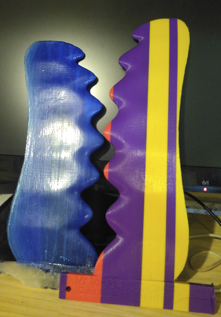
I think this one, called the AlbatrossWhale fin, will be more effective than the GullWhale fin.
Recent advances in build technology have allowed me to add another 25mm to the wingspan, while keeping the surface area equal to that of the Gullwhale-7-S-11mm fin.