room experiments with a ruler water to Greg Griggin coulit’s got a big hard on in the wa
  to back area distribution …but where it is vertically on the fin.
In a basic wa parts, Pic 4, a large low base that ris that to drive.
will do.
room experiments with a ruler water to Greg Griggin coulit’s got a big hard on in the wa
  to back area distribution …but where it is vertically on the fin.
In a basic wa parts, Pic 4, a large low base that ris that to drive.
will do.
Pics…<> g
Jupro
I’m in agreement with Greg G, area is the most important.
It’s not difficult if you are wanting to check area …just trace it onto graph paper and count the squares…take a balance of the intersected squares, close enough.
Then no matter what shape you can aim at a similar area.
Where you put that fin area in the water (how much, how deep, how it’s arranged) is the next challenge…
Double post, sorry.
Posts and vacced back piece for side fin.
Nearly 20 leading edge. Nothing too
If the concept works, I’m thinking how to escape complet fin shape to something more aerodynwhat…
Did you reduce fin height – while maintaining desired surface area – to adjust for changes in overall fin depth (below the board) that the struts might cause?
Looks interesting, I always get irritated when I put my fins in and there is a space between fin and board, then I loosen the screws and push it down tighter, ha!
Curious how this affects performance, is it supposed to make the board faster? Turn different?
The interaction of the two in-line post, may be the wildcard in this exercise. Not a fin for kelpy areas, though.
Brett,
Our fin discussions have inspired me. I need to find somebody to make a fin something like this for me to play with (below) for a Fins Unlimited box. Tilt axis 34-36 degrees from the vertical with a NACA 0012 foil profile.

@sto
If the fin area removed is from a turbulence area at the connection, then I’m guessing it won’t be missed much, and keeping the same overall area will make the board feel overfinned. Especially as the tab struts are going to add some area back. Just my guess - I already know this thing will go through mulitple iterations.
Hi Stoney-
You could put this fin together in 3d with a little help from Sway’s.
-member Hans wrote the finFoil program, member RDM has many fin bases up on thingiverse under Crapola Design.
http://hrobeers.github.io/finFoil/
http://www.thingiverse.com/CrapolaDesign/about
The foil can be done in finFoil in about 5 minutes…
Open the program, set the units and fin size (depth, thickness), drag in the reference images (fin shape and naca0012 foil) , scale the images using the green dot, and then moving the blue control points to be on the curve and the red control points to make the curve ‘bend’ the way it needs to go. You also get sweep and area calcs for free (no more counting graph paper squares…).
Once this is done, the file can be saved then downloaded to the finFoil online STL generator and uploaded as finished STL.
Take the foil STL and merge it to the fin base STL of choice (may have to scale units to get a match) and postprocess the combined STL at your leisure. The merging can be done with one of the free mesh-based programs, I use FreeCAD to design simple fin bases and Meshmixer to correct scale and combine STL files.
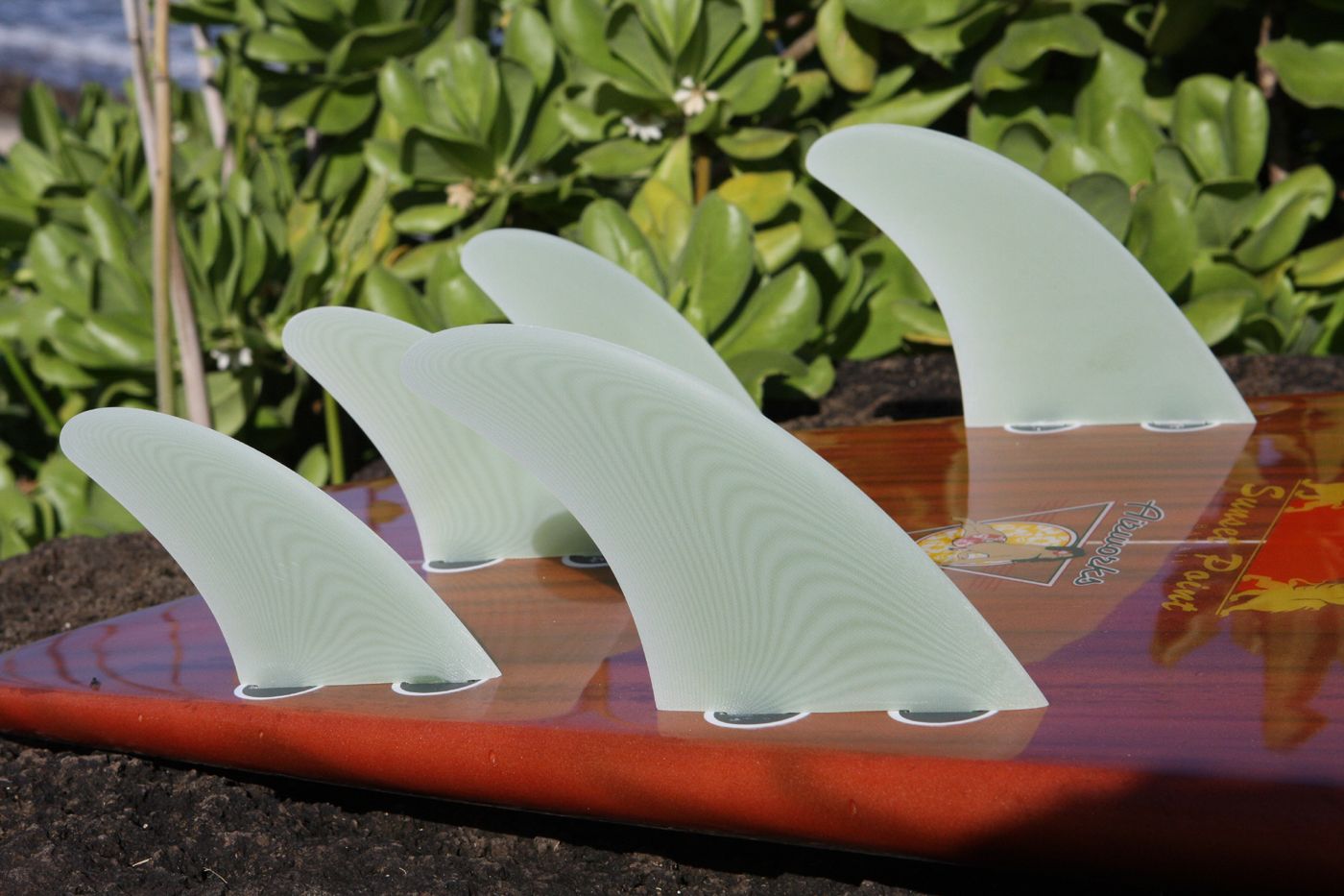
I did this process for a set of elliptical quads to fit Probox. I milled them from plywood and then covered them with fiberglass and resin.
Enclosing a pic of the bottom half of the finFoil screen, showing reference images and calcs for Stoney’s fin. I moved the black image over a bit for clarity, nomally it is place directly under the contour map on one of the side views.
There are other things finFoil can do- fins without reference images, asymetrical foils and one side flat, variable thicknesses from base to tip…best way to see it is to try it. Super simple user interface that yields outstanding results.
Even if you do not 3d manufacture the fins, pictures can be made and used as reference for hand cutting / foiling. Copy the screen image into a graphics program (Paint, Inkscape, etc.), crop, scale, and print to the size needed.
The NACA foils - http://www.swaylocks.com/swaylopedia/image/naca-airfoils
I am no expert, just a grateful user of free files and software.
“Huck, this Interference Drag is a big deal with yachts and means that there’s a lot of drag when the fins meet the board, but I don’t know how much drag there is and it’s been a bit of a design issue to work out just how make a fin without a base to find out.”
I make 5 fin boards that have no mention of drag - only unlimited top end speed mentioned . The fin being attached to and working with the board surface you are riding creates this . Riding up - planing - slightly on both , able to change angle at any time on a small drag free surface .
Fins sized and placed in their most efficient position , which happens to be just ahead and sized just below where they do drag . :-)
If I understood Brett’s discussion correctly, the turbulence at the base of the fin renders that area of the fin ineffective – reducing actual useable fin area by the thickness/height of the turbulence layer, 25-35 mm up from the base of the fin. What I believe he is doing is placing the original fin area above the turbulence layer. I would assume allowing the fin to ride deeper in the water would change performance regardless of the turbulence layer. Therefore, it seems like he is trying to maintain the original fin area above the turbulence layer while maintaining the same fin-tip depth. But fin-tip depth is just one variable to control.
Correct me if I am wrong Brett.
Youre right Stoneburner. Im keeping the area the same to see how much drag is lost or speed is gained. Im guessing there will be a 'free-er" feeling overall with a few changes to dial it in. Ill test the first one this week.
What I tried to explain is the base effect of what makes a board feel “Magic” since the late 60’s .
Great work as usual Brett.
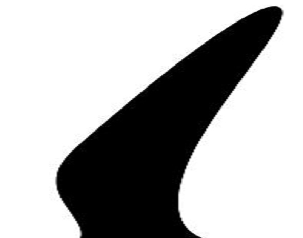
In regards to your initial question, I enjoy toying around with variations of fin outlines that nature has provided (the initial design work has already been done by the Grand Designer or by millions of years of evolutionary Research and Development - whichever you prefer). Biomimicry can’t be a bad place to start I figure.
For example, a peregrine falcons wing (see below).
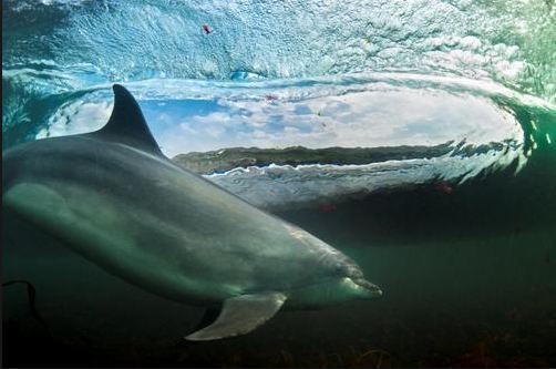
And if you disregard the reduction of fin area at the base required to facilitate control of the pectoral fin, dolphins seem to prefer the Greg Griffin style outline with no reverse curve along the rear edge (at least for their adjustable steering fins)…