How to design and make humpback whale inspired surfboard fins

Yes many fins have a long chord near the tip because of the pronouced sweep. I believe that high sweep fins behave like half a delta wing, using vortex lift to delay stall at high AoA, while generating drag for control. Somewhere you had written that you thought that the Gull Wing fin was one big tubercle, which is right because tubercles are small delta wings generating vortexes to dynamise the flow and keep it attached at high AoA. So the normal Dol fin planshape can also be seen as one half of a big tubercle… There are a lot of things going on at the same time, shifting regimes, blending together during the highly changing hydrodynamic situations encountered by a fin. As I said in a previous post, fins are probably one of the most complex applications of foils. 

You can search for foils here: In the drop down menu you can choose to order the foils by max lift/drag ratio for a given Rn. As an example I have set it up to look for symetrical foils around 10% thickness that are efficient at low Rn. 


I’m still going through the article in the first post line by line, taking detours when I don’t understand something.

It appears the performance improvement with tubercles is indeed very pronounced, not just on whale fin shaped objects.

I have some trouble identifying the exact foils mentioned in the article:

“The effect of leading-edge tubercles was investigated on the performance of two-dimensional foils based on NACA 0021, 634-021 and 65-021 sections (Johari et al. 2007; Hansen et al. 2009, 2011; Custodio et al. 2010).” 

The closest I can find is the NACA  63(4)-421 (NACA634421-il) airfoil at http://airfoiltools.com/airfoil/details?airfoil=naca634421-il

My understanding of the nomenclature for the foils is still rudimentary, can anyone who understand it better help out, please?

wrcsixeight has used a trailing camera to record footage of fins in action.

I suppose the rarety of visible fin vortices of tubercled fins is due to this.

Perhaps collecting footage of smooth fins in action would show more vortices, but who would want to waste surf session (and building time for the camera attachment) with inferior fin designs?

While writing the above question the answer occurred to me: I might! But I need to somehow get a more competent surfer than myself onto my board with the ‘FinEye’ camera in it.

Cheyne Horan is the obvious choice, I need to try to get him to do it. The ability to analyse the performance of his own fins in my board should be motivation enough…and I know he sometimes surfs 8ft McCoy Nuggets.

These two foils don’t appear to be in the site’s database. I think they’re talking about the symetrical NACA 63A021 and 65A021.

Anyway it doesn’t matter that much because the profile section of an actual humpback flipper varies so much and is not a really clean, consistant profile, being made of bone and fat. So the NACA references are just approximations. If I copy one of the flipper sections and analyse it, the performance results are going to be very bad.

I would not bother too much with the NACA nomenclature because you will find better, more modern foils for most thicknesses or applications. 

Posting below, NACA 63A021 and 65A021 and the flipper they studied to estimate the foils sections 


Would you like to send the file as attachment in Sways or should I pm you an email address?

Here’s the E168 and thicker E169 version :

https://swaylocks7stage.s3.us-east-2.amazonaws.com/s3fs-public/MrMik%20Gullwhale%207%2C%20E168%20foil.stl_.doc

https://swaylocks7stage.s3.us-east-2.amazonaws.com/s3fs-public/MrMik%20Gullwhale%207%2C%20E169%20foil.stl__0.doc

Thank you so much, WAO!

It will be interesting to compare them both in software and in the surf.


I spent some time reworking the tool paths I had for Mr. Mik’s g-whale. Changes to the tool path is mostly for finishing pass used a much smalled ball nose bit (~0.8mm radius) with much smaller stepover for a very nice finish off of the machine. Hopefully no sanding required.

I also changed up the base, carved it out and backfilled it with poly resin thickened with sawdust. This is due to the last ones predictably breaking. Sucks both g-whales broke on the paddle out. I was able to save them from Davey Jones Locker, but they are pieces of art now. The painted plywood one broke at one of the gaps in the ply and the cherry one broke along the grain. New base along with mostly being resin and sawdust with have a layer or two of scrap glass laminated onto it. I’ve had good luck with that type of base on past fins.

Like an idiot, I forgot to take pictures before I left for work today so that will have to wait until this evening.

WAO, I did have a question about the tubercle hydrofoil you made. I noticed that there were two spots routed out for what I am assuming the masts. Were you planning on using it as a double mast hydrofoil surfboard or was it for a completely different type of project. Also bonus question what are you using for your golden inlaid logo?


Edited to add some pictures. I put some resin on it as a quick cheater coat. I figured it would be better to do it while I have a little dam to keep the resin from running away.


Original Recipe or Extra Crispy?


Do you think that just resin and small wood chips (not dust) would do a stronger base than the wood-only tabs that I’m doing now ? I wouldn’t mind if my prototypes lasted longer without adding much extra work…

Yes it’s for masts, secret project for now, need more testing and at least one more prototype. 

Ah the golden logo technique is very special ! I route the logo, fill it with epoxy with opaque white pigment, then sand the excess epoxy TOO SOON, when it’s not cured enough, so the padauk dust ruins my immaculate white !

You’re welocome ! I’m eager to give back to Sways for all the stoke and inspiration I got from here.

So that the collection is complete, I will model a last one with the method that do neither valleys or depressions behind the peaks. Tomorrow with my morning coffee may be. So we’ll have all 3 modeling solutions.

The fin base and screw tabs see incredible loads.  Any non fiber reinforcement is doomed for failure sooner or later.

The Load must be spread over a wide area, both lateral stresses, and stress on the fin tab(s)/roll pin from any frontal or rearward hit.


Also the roll pin, is best eliminated in favor of two tabs in my opinion.  The roll pin needs to be located precisely so that the bottom of the fin is jammed flat against the bottom of the box at the same time the pin is touching the top of the groove within the box. Much easier styped, than accomplished.

Also it seems there are some differences in the location of the groove in boxes.  The ball spring plungers from the early days of MrMiks fins would be pushing on the edge of thge bottom of the groove in my box, trying to push the fin upwards out of the box.  as such the BSP’s were a hindrance to a tight fit and would seek to help eject the fin from box in my board, and the BSP holes also induced weakness in lateral strentgh and fin tab strength as well.

Without the ability to print/drill holes or square up from base of fin into fin body to add carbon bars/rods, then fiberglass needs to be run from the sides of the fin into the base, and a good amount of it which would require thinning of the wood below in order to not sand it all off to get it to fiit


Super hard and strong woods will of course last longer with teh grain going from tab up into fin base, but will fatigue and break  This wood grain orientation also makes the screw tabs on single fins weaker.  Plywood is generally so soft that even encased in epoxy it will compress and allow rocking of the fin on teh box which then accellerates the wobble and stresses involved on the weakening tab while allowing it to suck water and get even softer.


Having fins break at the base or the tabs just shearing off barely touching sand, is a session ruiner.  Even with another fin on hand one needs the tools and light and perhaps reading glasses to remove the broken bits and reinstall another.


I’ve had two more sessions on my 6’11 with a new toe side rail fin and either the half size GW fin or the half size AW tubercle fin in the center box.  My new toe side rail fin has more surface area than previous, with more surface area  in the tip, and every frontside wave I got, when going slow, it seemed the board pivoted around that larger rail fin and simply pushed the tubercle center fin sideways for a lack of drive and tail drifting shoreward.  If I was going faster then laid into the bottom turn it felt great, but going slow was frustrating, and generating speed on mushier gutless waves was a lesson in futility as it seemed there was little fin to push off of.  

The first session I got so frustrated with the lack of ability to generate speed, as the swell had not really filled in as hoped at that time, I went back and got my longboard with one of the most recent GWhale fins,  and laid into a few backside bottom turn top turn combos that felt simply awesome and reminded me just how awesome this fin feels.

I’m currently  thinking  the Gwhale fins cut to half size used in shortboards as center fins is not a valid strategy for gutless conditions where one needs to generate speed.  I’ve moved them back overhanging the back of the box, but I’ve found on my 6’8" that I liked the smaller center fin moved unnaturally forward. So moving the tubercle fins further back to account for the high aspect ratio is widening the fin cluster and at slow speeds it is not feeling good.  Once I am going at a good clip it feels good, but on my toeside rail on the drop, avoiding a bottom turn there is a lack of drive, and that slippery feeling prevents accumulating more speed which  could then eliminate the slippery feel.

I generally only ride this board in chest high +, but eagerness to try the board and new fins has me trying it in lesser wave size, and I am struggling.   Also quite rusty due to Covid closures, which are happening again as cases surge.


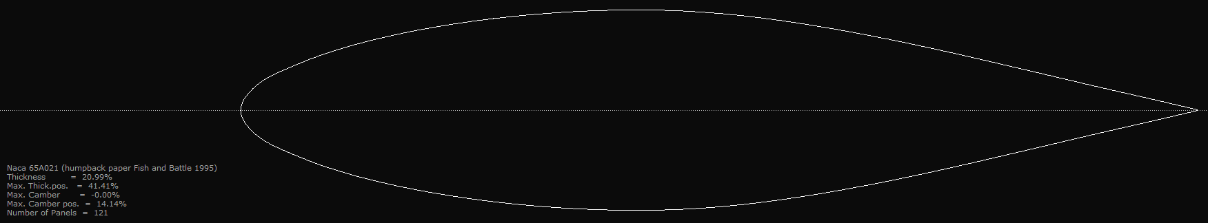
I am not quite ready to write off the Drela AG10 ‘batfin’ without more sessions, but I think its flat sided  sharkier  predecessor, was faster and crisper.  I glued a zippered fin size pocket to the thigh of my Shortjohn, and will carry at least one spare center fin and perhaps the sharkier toe side rail fin in future sessions.


Iam also thinking I should modify a Gwhale fin to sit further forward and be deeper.  Something about the fin being too far back on a round pin is bothering me.


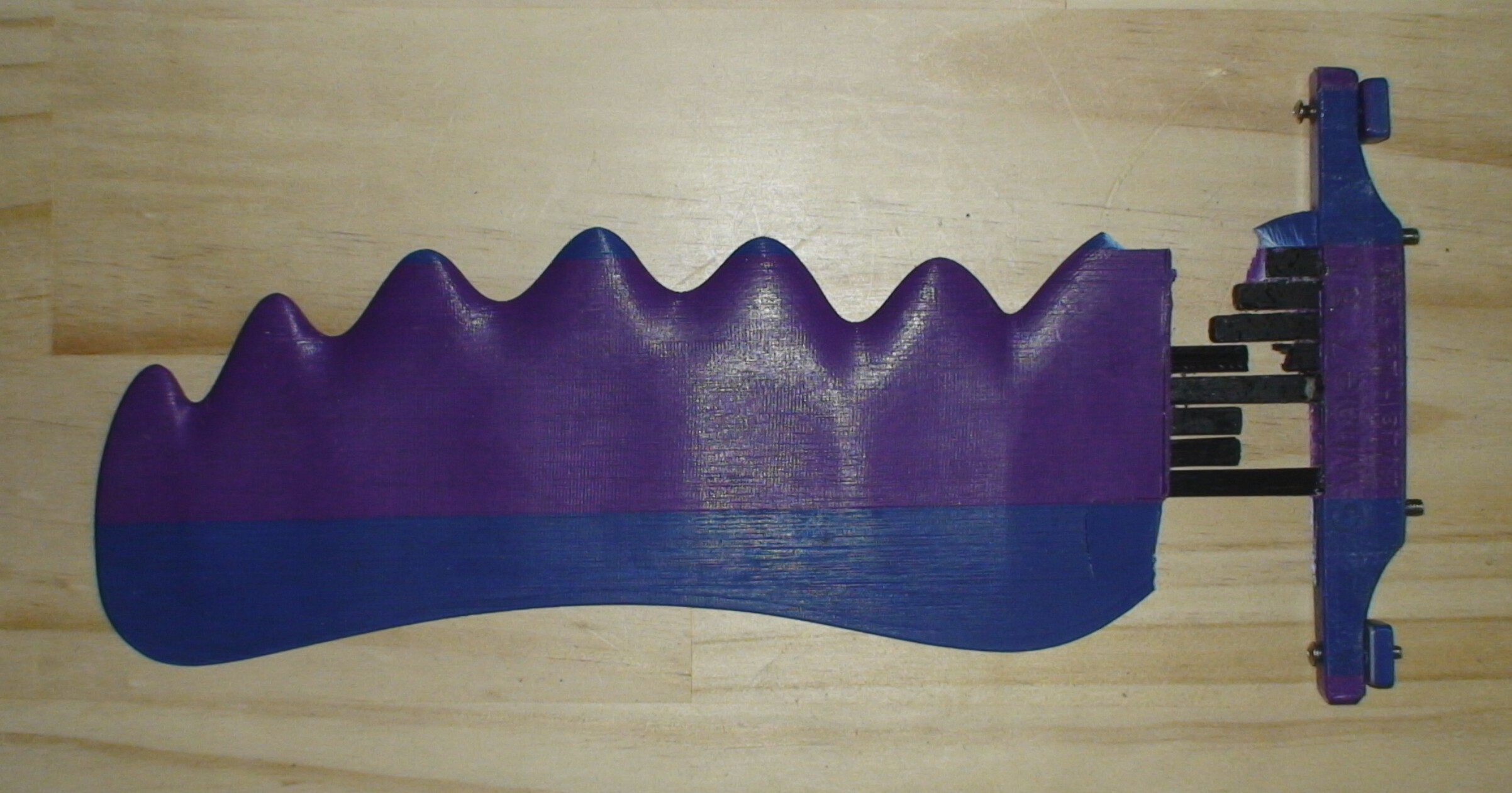
Also while the super high aspect ratio Gwhale fin works insanely well in my traditional longboard, perhaps a more maneuverable multifin shortboard needs fin rake and tip area to force larger turning radius and more drag,  and modifying the Gwhale from full sized fin to half sized shortboard center fin,  is a formula which cant really translate.


The tubercles and one’s leash are also an issue. My leash much too easily sinks and gets caught on a tubercle, and even when I notice it when sitting on my board, and try to extract it while sitting,  I cant unless I get off the board and undo it by hand.  I’ve tried neoprene sleeves to make  the leash float with little success and with more drag .  I’ve an old ‘back up’ leash from the early 90’s( XM) which is much better in this regard.

My fear with tubercled rail fins is the leash  getting caught even easier, and trying to ride a wave with leash wrapped around a fin is frustrating to say the least.  I’ve not used a leash on my Longboard so it has not been a factor on that.


This fin snapped yesterday. 

I used an experimental method to insert the carbon bars into the fin with bees wax and gum turpentine. The fin was printed in Oct 2018 and the carbon bars were inserted in April 2019.

The fin snapped under similar conditions that usually make them snap under wrcsixeight’s feet: Pulling off a wave with a forehand turn, the fin snaps at the top of the wave.

The bars still smell of turpentine, I made the wrong assumption that the turps would evaporate through the PLA faily quickly and make the wax more stiff and sticky.

None of my fins which have the carbon bars glued in (either epoxy or polyurethane) have snapped, yet.

There are also longitudinal carbon bars in the base, they did not break because they experience no significant load under the surf move described above.

My resin cheater coat turned out a little thick. So I ran my finishing pass again and I am very please with the results.

I am also very pleased with how the base has turned out so far. Next ones I’ll probably use some chopped/milled fiber for even more strength, but sawdust was all I had on hand to thicken the resin for the base.

Here are a couple pictures from after the second finishing pass. Definitely a big difference when using plywood.

I’m going to document the full process for the backside. In case anyone wants to try and duplicate and/or suggest improvements. At this point there are a lot of steps, but a huge improvement of end product.


I note there are no flanges at the fin base.

Also, it seems that the Eppler 168 and Eppler 169 files are identical. 

But I might be mucking it up in OpenScad, not sure. Maybe I have a stray ‘resize’ command somewhere.

Can you please check if you uploaded the correct files?

Ouch, i had exported the E168 twice. Reuploaded the E169 now. The first should be 11.36 mm thick and the second 13.38 mm.

Yes I didn’t model the flange, I simply applied the foils to the planshape. What is the flange for, strength ?

The files now works as expected, thanks! 

There is an ever so slight difference between the Eppler168 and Eppler169 fins, even when I adjust the thickness to be the same, because the Max Thickness is at 26.7% vs 26.5% chord. 

Both of them have a slight concave fore of the trailing edge.

Having looked at this in more detail now, I cannot really say what foil I used for the G-Whale7-FRR. I started with tracing Eppler 168 into finFoil, but then I tried to work out the best thickness after an actual fin was printed, so I measured chord length and max thickness at each tubercle and at each valley. I averaged the results and adjusted the overall thickness of the fin so that it’s close to E168 (tubercles) and E169 (valleys) on average across the wingspan. I did not pay any attention to where the thickest part is (meaning at what % of the chord length). The foil is really customised for the particular plan shape. 

Unfortunately the WAO - E168 does not work perfectly with my standard UTFB carbon bar system, it is too thin in just one spot, so there is a surface breach when I shift the carbon bar hollows in OpenScad, see attached screenshot. The WAO - E169 fin is thick enough so I would not have to make changes. There will not be a surface breach in the actual printed fin, but too few layers between the hollow and the outer surface cause surface imperfections. Every carbon bar is fine-tuned to within 0.4mm. I think I also adjusted them so that I can make thinner versions without changing the bar system. 

The E168 is probably closer to my G-Whale-7SRR (11mm thickest part), so I’ll render and print one. I find it difficult to get a good impression just from the computer screen. The differences will be much more obvious when I have a real fin in my paws.


The flange does not add much strength, maybe none at all.

I just figured that airplane wings have flanges at the fuselage, fish fins don’t come out at 90deg angles from their bodies, glassed-on fins have flanges, bird’s wings are blended in / flanged etc etc.

And it is very difficult to make flanged fins, and harder to make them fit in a fin box, and even harder to make the same fin fit into most finboxes. So, just like the flat sided side fins, I guess that flange-less fins are simply an inferior design dictated by the production methods available.

But I have no proof for that and I do not even remotely understand the hydrodynamics occurring at the fin / board boundary. 

May be not a concave but the curve is flatenning out at the trailing edge. It comes from pulling the two sides of the foil away from each other to create some thickness at the trailing edge, instead of sanding some of it off, which would make the foil shorter. At our Reynolds numbers laminar flow is already slightly separated at the TE, even at 0 degree AoA, so adding thickness there (up to say max 2% of the chord) doesn’t decrease the performance. On the contrary if done properly one can improve the (2D) caracteristics of the foil, without otherwise changing the max thickness and it’s position.

Posting below a comparison of the original E168 and the 1% chord TEG (trailing edge gap) version. Then graphs comparing the perfomances. While the L/D ratio stays very similar, the lift vs AoA and the drag bucket are improved at our Reynolds numbers for 3 and 10 m/s.


I didn’t think about the carbon rods, if you need modifications I can do them quickly, so you don’t print something that you can’t use. If you have any other ideas, like different foils that you’d want to try for your G-Whale, let me know.

https://swaylocks7stage.s3.us-east-2.amazonaws.com/s3fs-public/E168%20+%20E168%201%25c%20TEG_0.jpg

https://swaylocks7stage.s3.us-east-2.amazonaws.com/s3fs-public/Lift%20to%20Drag%20vs%20AoA%20-%20E168%20+%20E168%201%25c%20TEG.jpg

https://swaylocks7stage.s3.us-east-2.amazonaws.com/s3fs-public/Cl%20vs%20AoA%20-%20E168%20+%20E168%201%25c%20TEG_2.jpg

https://swaylocks7stage.s3.us-east-2.amazonaws.com/s3fs-public/Cd%20vs%20Cd-%20Drag%20Bucket%20-%20E168%20+%20E168%201%25c%20TEG_0.jpg

That is fantastic! How do you calculate these curves?

Now I recall that I had to do a number of small changes in finFoil until the trailing edge was 3D-printable. The TE on your modified E168 printed OK, but only just. The problem is that the printer tries to do fancy stuff to make a thinner TE than what can be done with 2 x 0.45mm extrusion widths. The TE might be slightly flexible on the E168 fin. 

The foils of the unchanged E168 and E169 look concave to me between middle and trailing edge, try placing a ruler on the screen.

In finFoil, the minimum thickness can be set, it has a similar effect to your modification, but it also affects the leading edge, giving it a small flat at the front. Not a problem on the G-Whale fin with 0.2mm printed layer height, but it could matter for thinner fins and if printed with thinner layers.

The margins I designed for the finFoil version are wide enough to not cause an actual surface breach with your E168 version. Just a little surface imperfection that is smaller than the imperfections caused because each external layer needs to start somewhere and makes a little ridge.