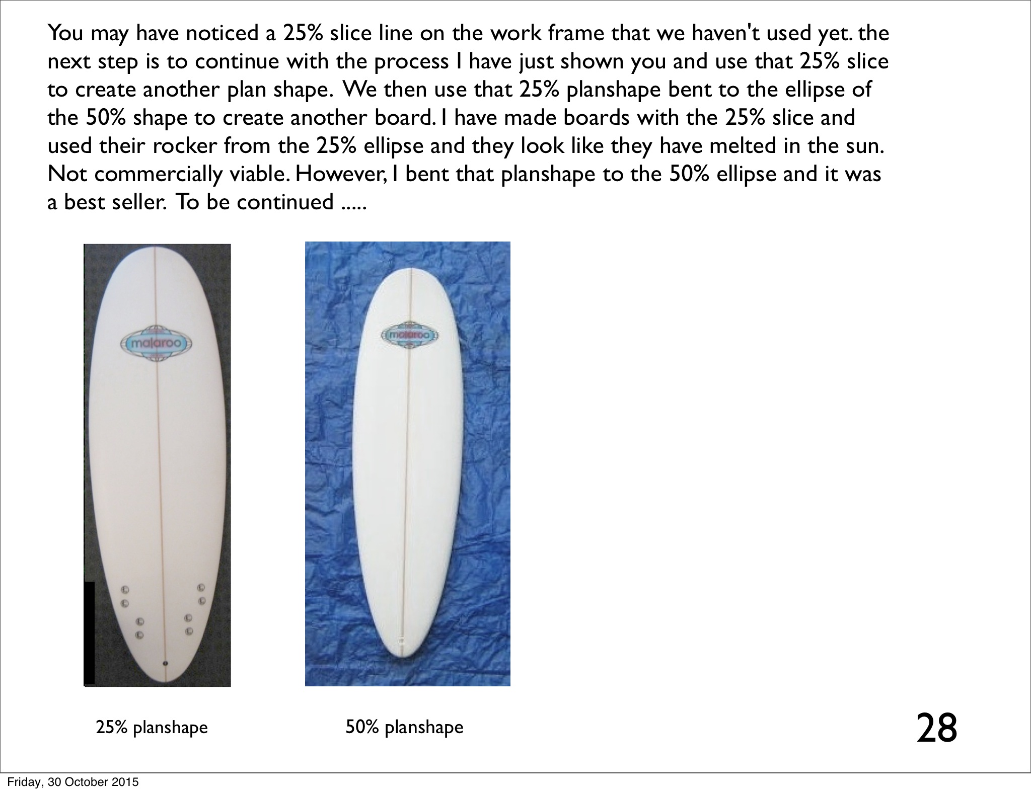
page 28
Hi Malaroo,
With bending to 50%, I’m not completely sure what you mean.
Would the following be similar to what you mean?
- Use the 25% cut to create the planshape
<img alt="" src="http://hrobeers.be/images/shape/openscad/geom_2/5.png" style="height:429px; width:870px" /></li>
<li>Project the planshape

<img alt="" src="http://hrobeers.be/images/shape/openscad/geom_2/6.png" style="height:429px; width:870px" /></li>
<li>Use the 50% elipse to cut the rocker

<img alt="" src="http://hrobeers.be/images/shape/openscad/geom_2/9.png" style="height:429px; width:870px" /></li>
Hi Hans
Your on to it quickly, I’m not sure your solid pic is right, I can’t tell quickly enough from the pic. Create a surface (not the solids) of the 50% ellipse, like you did earlier instead of a solid, and then project the outline (not the rotated side viewed rocker) but the top view outline of the 25% planshape, project the outline through the 50% elliptical surface. (have you alerady done a 25% outline?) The new intersection line will be the 25% planshape bent to the 50% ellipse. I will post pics later as I have other commitments now. (sorry to be limited to a verbal explanation) … well done Hans.
Hi hans
The first two steps are right, But I’m confused with, use tthe 50% ellipse to cut the rocker … to cut the rocker? My head is spinning.
Yes, also the pic might be confusing as these are pics coming from the last series.
What I was trying to ask: Is it correct to use the 25% ellipse to cut the cylinder to create the outline, then poject it flat, extrude it and then cut it by a rocker created by cutting the cylinder with the 50% ellipse?
The problem is that OpenSCAD doesn’t support 3D surfaces with 0 thickness, and it has no bend feature.
With cutting the rocker, I mean the intersection in the third pic.
I am totally lost about Malaroo’s fgure with many numbers (dimensions).
But I think I am beginning to see where the transect and rocker bottom rocker curves are coming from. Twenty-five and 50% ellipses from a partial cylinder transect? Twenty-five and 50% of what?
It’s 50% and 25% of half the board width ![]() (see image)
(see image)
The respective ellipses are the ones created by cutting the cylinder to that point.
It also took me some time to get it, but going through the procedure yourself helps in understanding.

Thanks Hans. That helped a lot. I will post some 2-D graphics of my interpretation in a few days. Then the 2 of you can correct me if I am wrong.
Hi Stoneburner
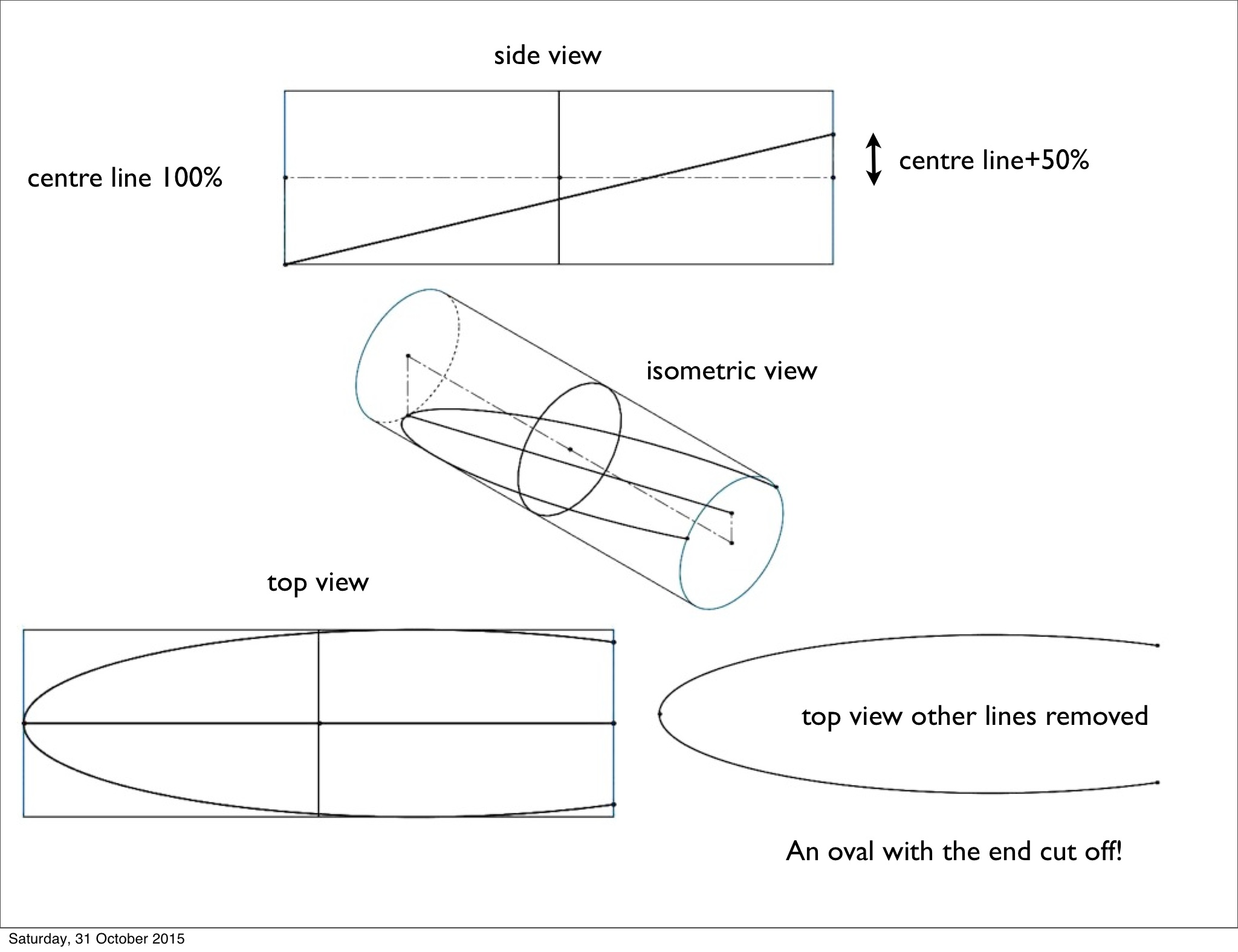
Hans is right, and your question is important, I’ll try and explain why I call the centre line 100% (sometimes). If you do a slice from the outside to over the centre line, you start to get ovals that have been cut off, I’m sure there is something to that but I haven’t pursued that something yet. So 100% of elliptical options that dont repeat and get cut off are between the centre line and the outside. Here’s some pics of a line that is +50% over the centreline.
Hi Stoneburner
I don’t know how to add pics and text in order on one post … so
Further to that is the question of, Why all the measurements? I did the board in a concept rather than in dimensions because with solid works files you can go back and change sizes (dimensions) and the whole thing up dates, so you type in the dimensions of the board you want and … there it is. In this case I have made the dimensions proportional, the width is 100 (Why didn’t I make it 200 so the centre to widest point is 100?) well … for a goos reason. As I explained in an earlier post, people wanted certain lengths and widths, eventually I realised they were in a proportion of phi … 3.14. So the length of the board is 314 times the width of the board. For easy maths I made the width 100 (and for confusion on the proportions concept) proprtions and actual measurements used are two different things. So when the width is 100 that is halved and the centre line too widest point is 50 and half that for a slice line is 25 and half that for the other slice line is 12.5 … and 6.25 (but I put 6.35 by mistake). Being human has its limitations. Here’s a pic showing the length of the circle.

hi Stoneburner
I’m very messy with explaining this …
So the width is 100, create a circle that is 100 wide, the circle lines length (circumference) is phi (3.14) x 100 = 314. (that’s just how it is) make that the length of the board 314!
Ofcourse it doesn’t matter if you change the proportions, it’s just that it was most requested without people knowing the proportions, so there was some sort of natural relationship there.
Hi everyone
Just letting you know I have’t forgotten you, I am working on a detailed response to Hans question about intersecting 25% and 50% planshapes and ellipses … that involves downloading and understanding openSCAD as well, and the fins concept for greggriffin and jspr and a response to wooddaves great posts and the rails for stoneburner … in other words … it will take a bit of time.
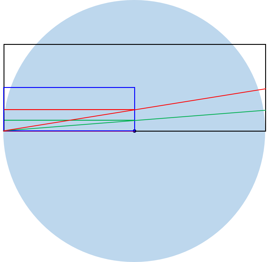
2-D interpretaion, is this correct?
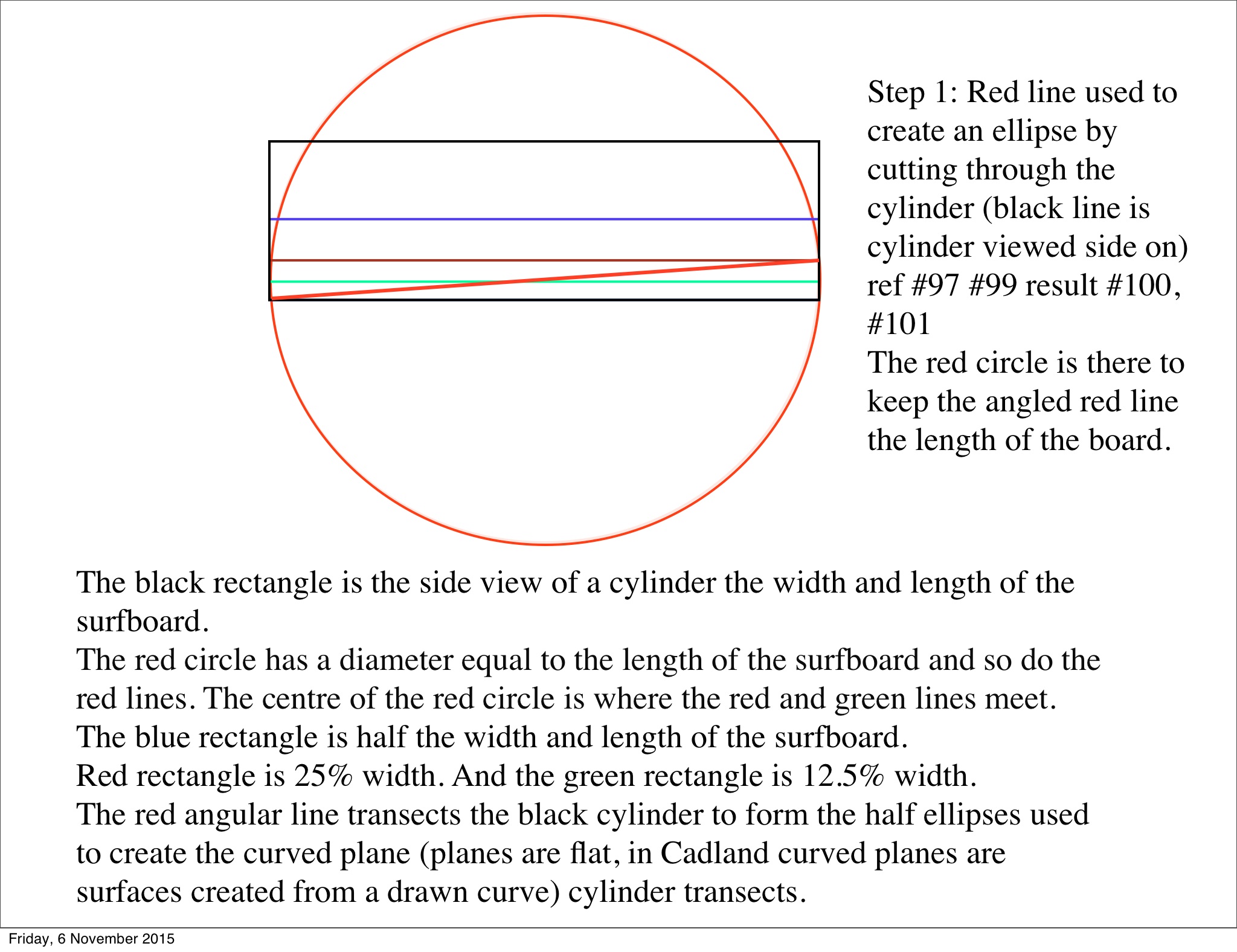
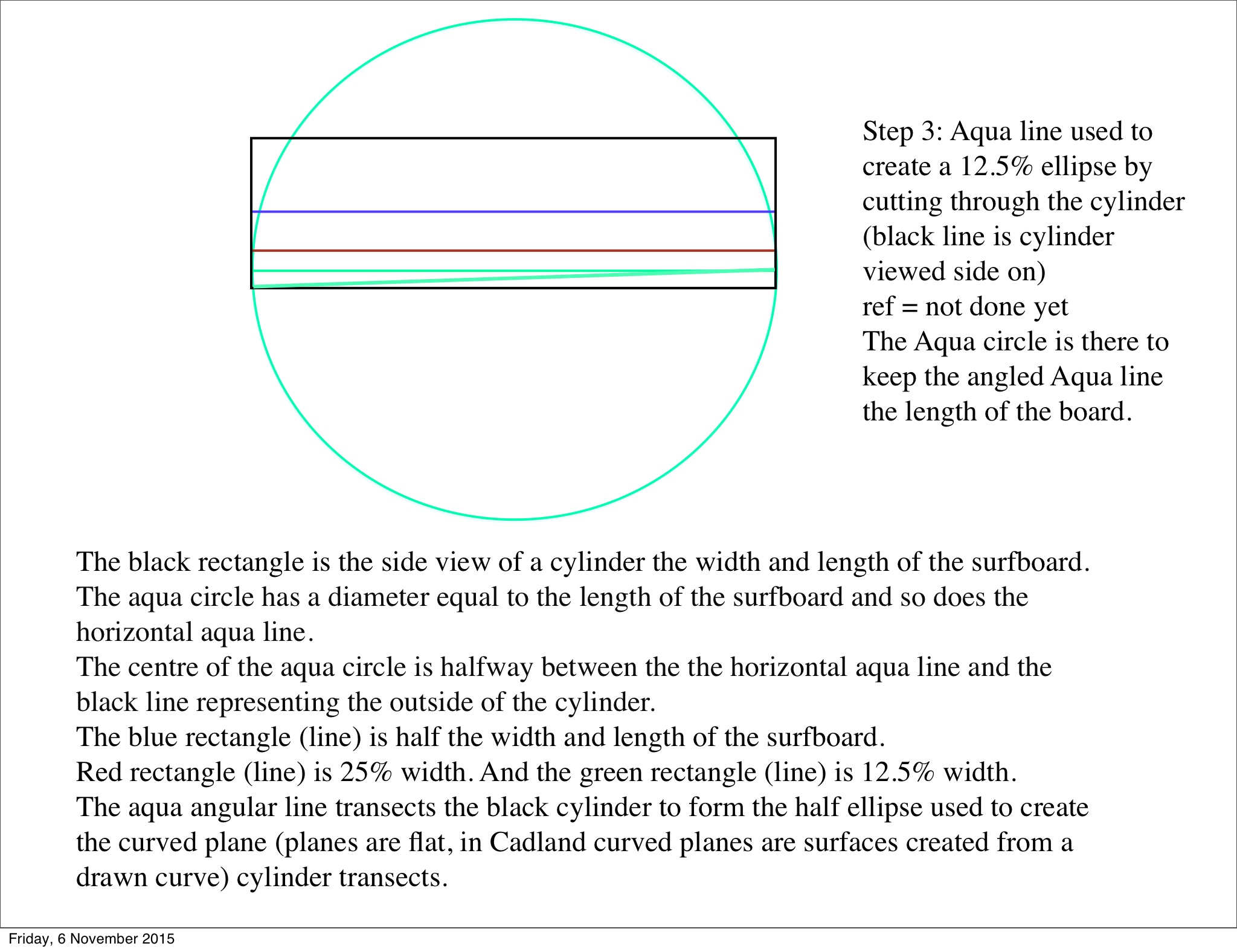
The black rectangle is the side view of a cylinder the width and length of the surfboard.
The light blue circle has a diameter equal to the length of the surfboard.
The blue rectangle is half the width and length of the surfboard. Red rectangle is 25% width. And the green rectangle is 12.5% width.
The red and green angular lines (extended diagonals) transecting the black cylinder form the half ellipses used to create the curved plane cylinder transects.

Hi Stoneburner
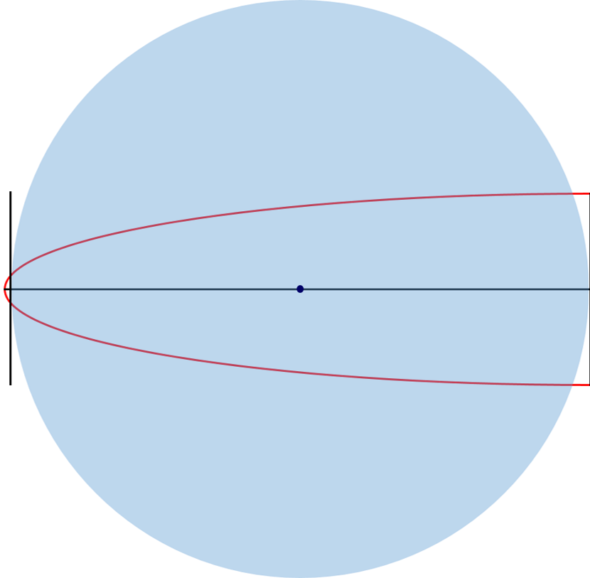
Thanks for your response as you promised earlier. You have put a lot of effort into it and I can see how my info is confusing you and the others. 3D Cad is the mixture of 2D cad drawings as the drawings are done in 2D on planes, I think you have drawn the side plane and the top plane. (I’m not sure why you extended the angled lines, that’s what confuses me)? I will try and explain it in the form you have presented. Basically as I see it at the moment, you have just misunderstood the reason for the circles, (your light blue circles), and therefore not centred them correctly. They are only there to control the length of the red line used to slice the cylinder and (in the top view) to cut the ellipse to the length of the board. If I’m right then the following might clarify things for you. I hope so. You obviously want to find a workable 2D representation.
I see it now.
I debated whether my 12.5, 25 and 50% rectangles should be the length of the board. But it seemed like the half ellipse lengths would be too short.
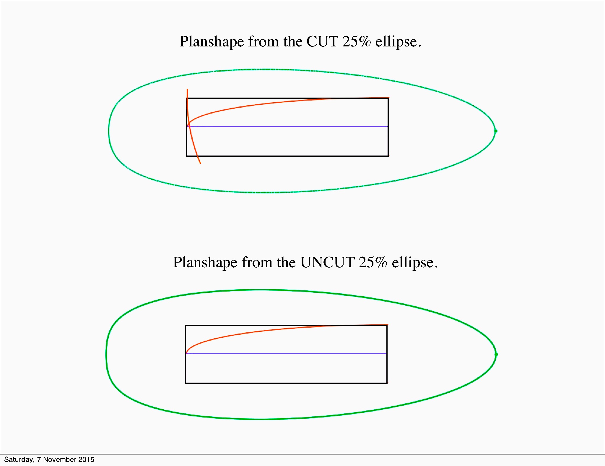
I see what you have done centering the hypotenuse to create a half ellipse length that you can clip the curved tip off the half-ellipse with, creating nose kick with a gentler tip angle. You want the hypotenuse to be longer than the planshape length though.
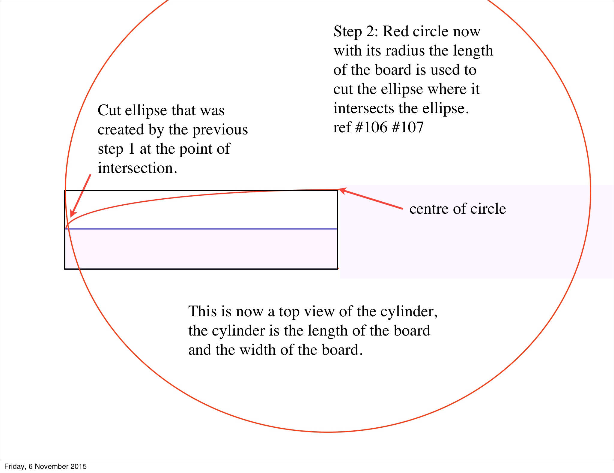
I also figured using the diameter to clip off the curved end of the half ellipse was not really creating an elliptical chord the length of the board (but was close). Using a board-length radius to clip the end off the half ellipse solves the correct chord (board) length issue.
While playing with all of this, I came up with another method for using ellipses to create rocker curves.
I will stay tuned for new episodes.
That is what is so unique about your method. The more vertical the nose-kick angle is, the wider the nose tip gets.
“While playing with all of this, I came up with another method for using ellipses to create rocker curves.”
Thought you might be interested Malaroo.
This is what I came up with using PPt and ellipses to create bottom rocker curve.
Board length, 7’6"; tail rocker, 2", nose rocker 4.7".

Hi Stoneburner
That looks good, I’ll do some rockers with Surfboard geometry and show a conparison … it would be good to measure some real rockers that work and plot the points in 2D to see the comparison as well.
I’ve been working for days on a response to Wooddave and I will concentrate on finishing that first. OMG! I’m going crazy.