On to the next level…
.
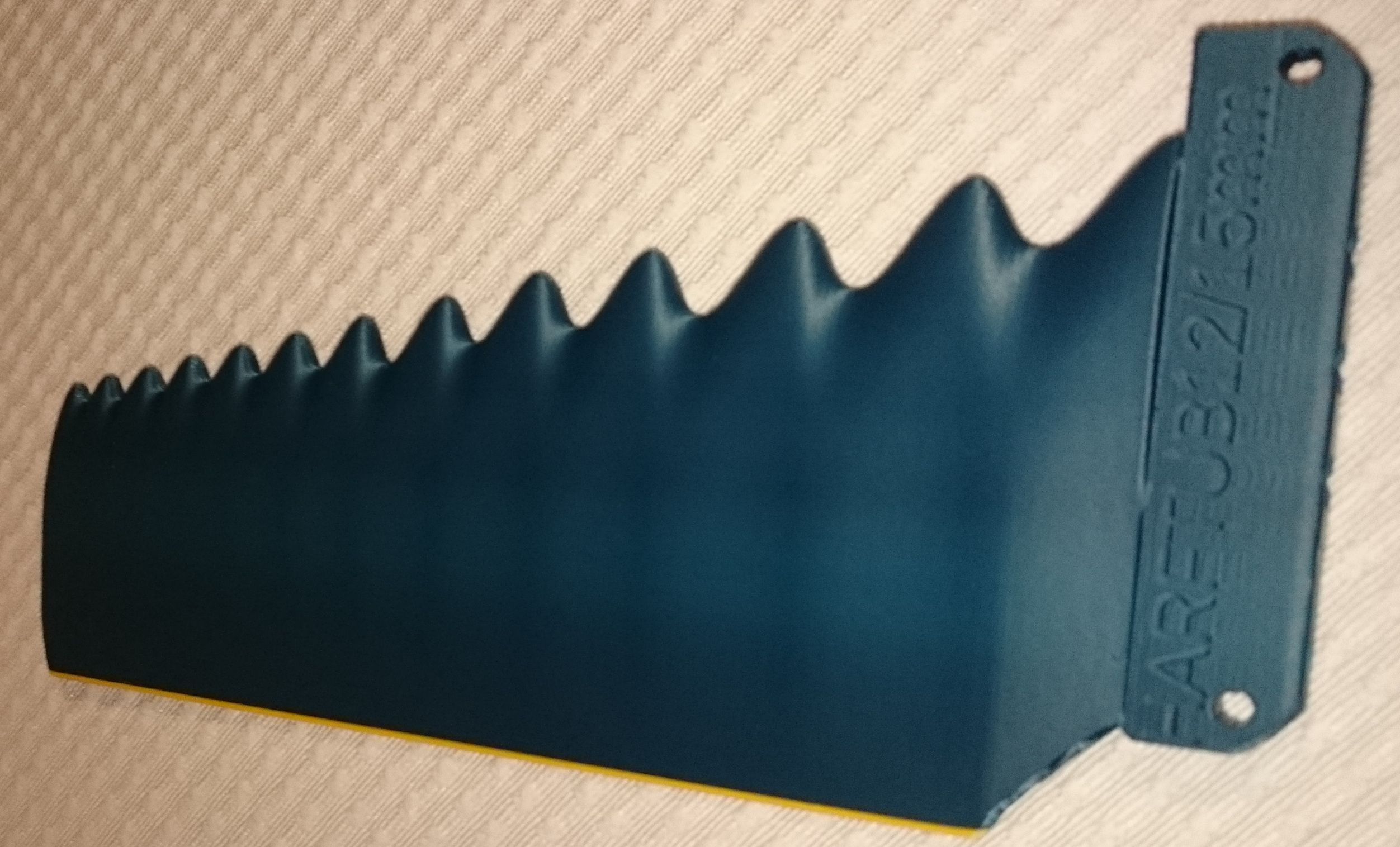
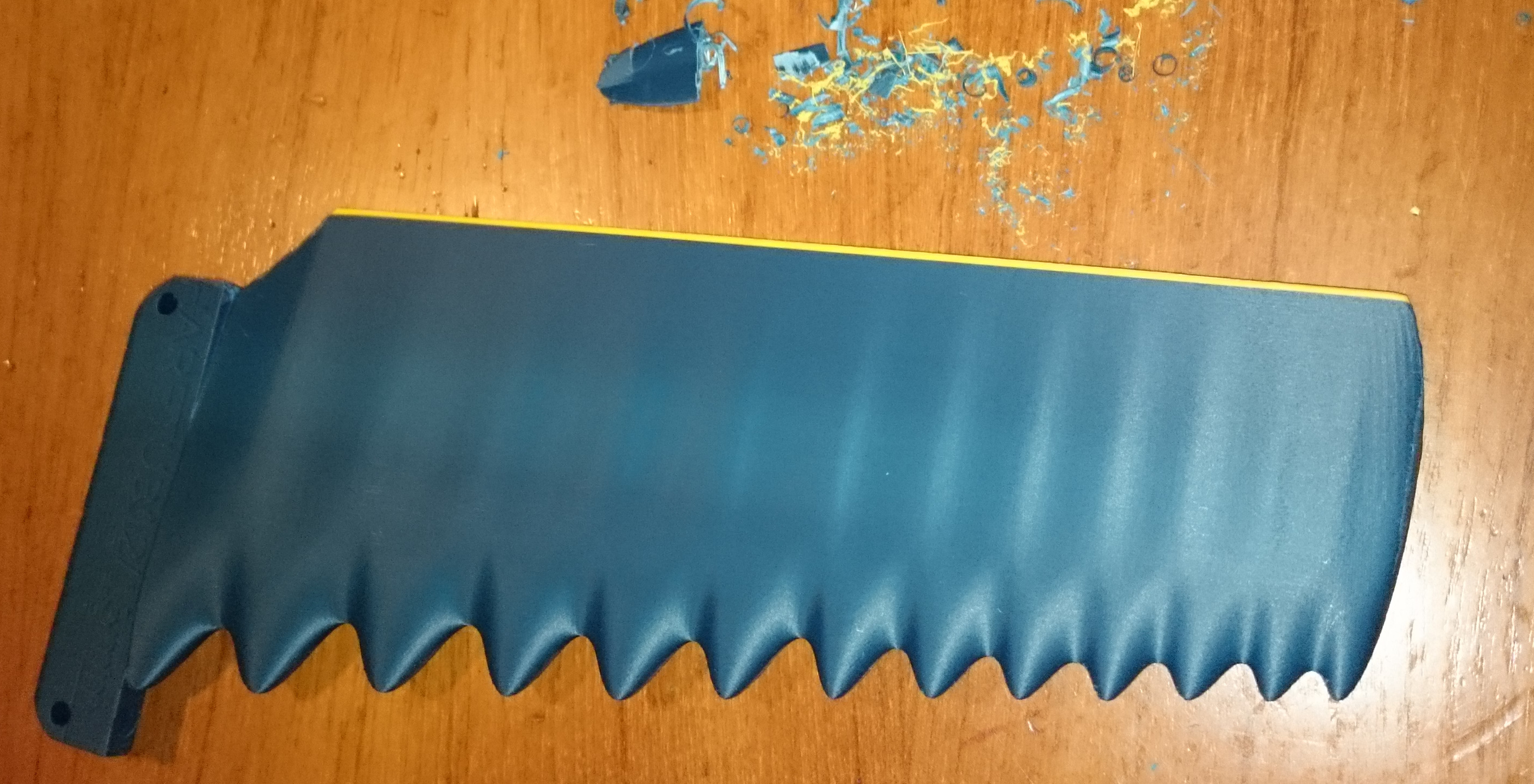
HARFTUB12 @ 15mm width. Printed from new material, using slower print time.
.
Less manual processing required after printing, but that’s not entirely certain until I have removed the support system and prepared the fin to completely ‘surf-worthy’ state.
.
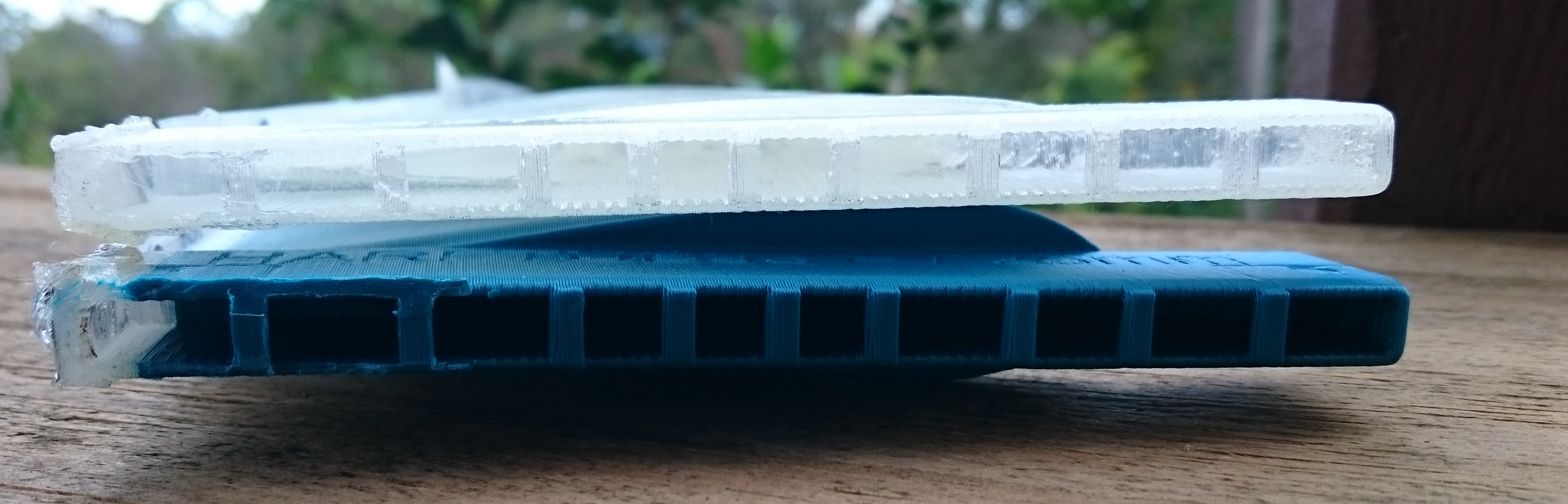
The material might turn out to be less strong than the PLA I used before, but I’m confident that the inner structure of the fin does more than compensate for this.
.
Buoyancy has not been tested yet, the thickness of 15mm is going to be borderline in that regard, and it depends on the density of the new material. I guess it will be a close call, maybe floating in salt water but not in fresh water. In any case, it’s not likely to be buoyant enough to give a good chance of finding it again if lost in the surf.
I managed to snap off the forward part of the fin tab while trying to force the fin into a board after applying too much hot melt glue. HAHAHA!
That method works really well though if you don’t go too far…
.
Anyway, I printed a new fin, with improved internal structure, time will tell where it will break next, but it will need more force before it breaks than last time. Because another weak spot is fixed.
.
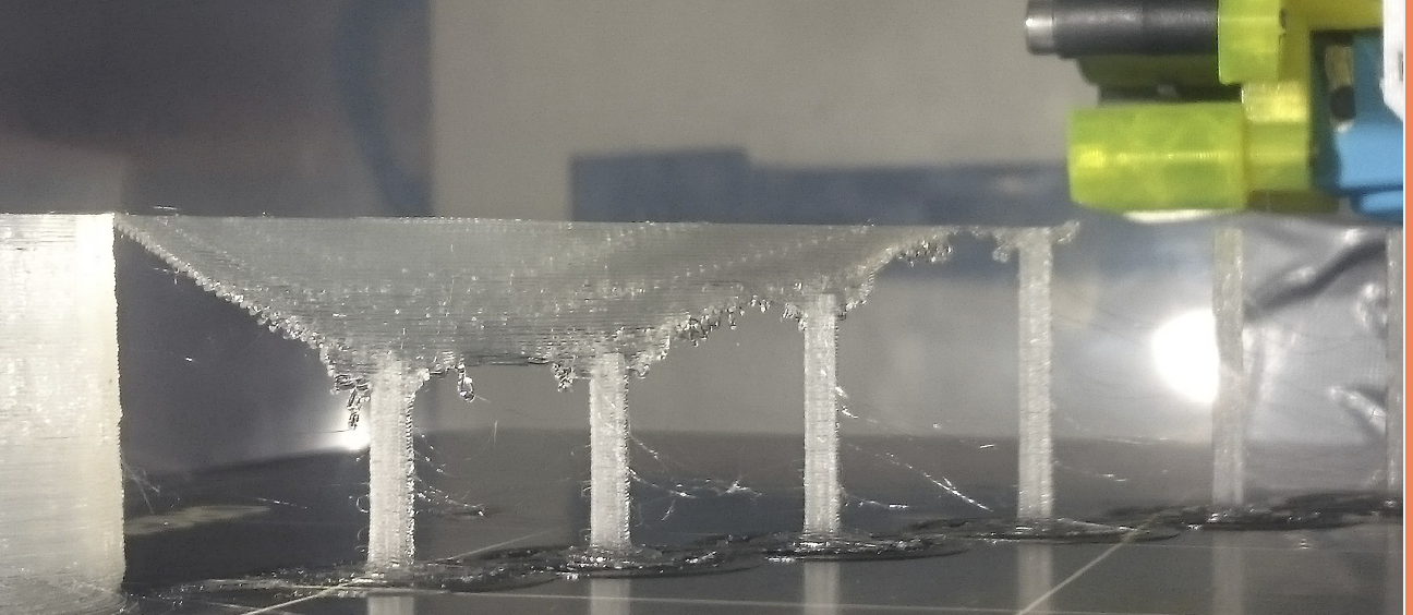
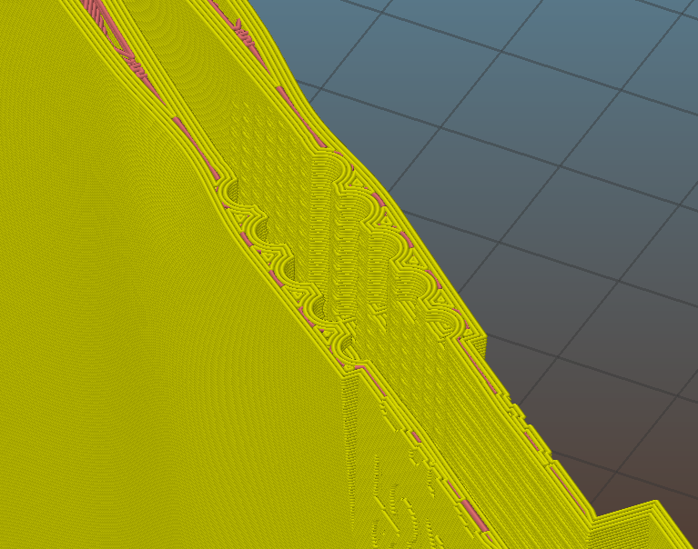
I have refined the support system to a point where not very much further gain will be possible:
- load spread nicely over the PEI sheet, I can print in the same spot repeatedly. Maybe I might have to move the print around if repeating multiple prints, but the bubble of PEI is very shallow now.
- weight of printed fin is 174g with supports, 167g after whittling supports off.
167 ∕ 174 ≈ 0.959
That means less than 5% of material is wasted during the production process. And I’m still using only renewable and biodegradable printing materials.
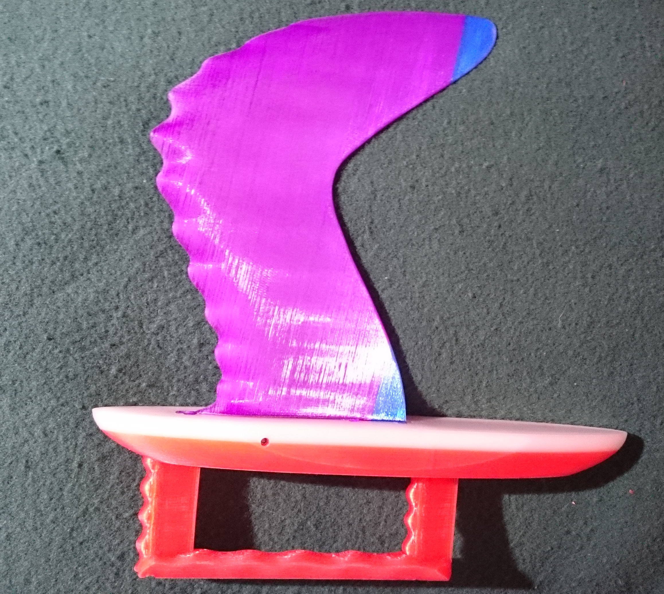
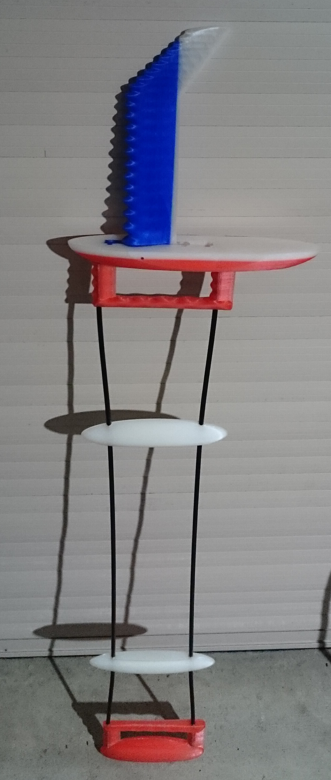
The fin tester is ready for action.
Both ends can be used by themselves for under water testing, or the whole rig put together is used to walk along a swimming pool holding the fin in the water…
The bigger end simulates a surfboard bottom, in case it makes a difference, for example for comparing fins with or without a cut-out at the trailing edge.
The smaller end is just that, smaller, to reduce drag, maybe that allows to feel smaller differences between fins.
The white parts in the middle have holes a bit closer together, so that they bend the carbon tubes and hold everything securely together, without glue or need for tools.
Back to “Casting Hybrid (Lamination) fins”…going full circle, or rather up one level on a spiral around the core idea of the UTFB.
.
A year or so ago I was trying to make a Universal Tough Fin Base (UTFB) to get around the problem of poor fitting in the fin box, and difficulties machining a truly straight fin tab with hand tools.
.
Then I tried to cast UTFBs in moulds. The resulting UTFBs were intended to be inserted into freshly cast fins in another mould.
.
I also 3D-printed ‘mould-moulds’ to make silicone moulds for making UTFB’s.
.
And then I 3D printed fins and corresponding 3D printed UTFB plugs.
.
Now the penny has dropped, and I have developed my CAD skills enough to pull off a combination of all these techniques into a new approach:
.
I CAD design the UTFB as a hollow space within the fin and fin tab, and 3D print it. So the mould for the UTFB is inside the 3D printed fin, ensuring a perfect fit every time.
.
Carbon tubes will be inserted strategically to increase strength further and to spread the shearing loads, and then casting of a hybrid fin will proceed.
.
The question is how to best imitate the ‘lamination’ part. My understanding is that the best strength is achieved when the fibres are only just saturated with resin, but no excess resin is left in the fibre. I cannot layer cloth or arrange fibres in an orderly fashion inside the narrow UTFB space, so I think a slurry of epoxy resin with fibres will be the go. Just runny enough to allow air bubbles to be manipulated to the surface with a chop stick, but not so thick that it bends the tab wider than it should be.
.
The square parts arranged along the UTFB opening will be sanded off later, their purpose is to keep the sides of the fin base at the correct width while it is being filled.
.
Any suggestions which fibres would work best with epoxy resin into this space?
.
I have a variety of leftovers from previous projects: Carbon/kevlar cloth, fiberglass leftovers, carbon cloth, and a variety of silk skeins.
.
Any suggestion for how to achieve the most strength in this cast would be much appreciated.
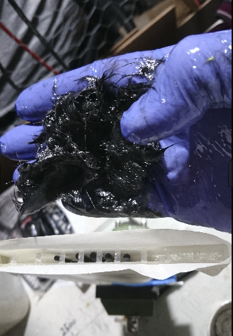
This is the UTFB made from carbon rods, epoxy resin and chopped carbon fibres.
.
It is a lot of work stuffing the fibres in, but I think the base will be sufficiently tough that way.
.
Still working on improvements to make production easier and optimise strength with minimal material use.
.
Remains to be seen if it still fits in a fin box when I have sanded it back…
Mr Mik, it’s amazing work to put all the skills and knowledge of 3-D orienting together and then work out how to create something that actually works.
The ones you sent to our family are all still being used and swapped around. Nothings broken so they’ve been well made. Thanks !
Good to hear they are being used and have not snapped off yet!
What is the biggest surf they have been used in?
Any barrels? In my experience, that’s when weak fins snap off, when the wave is trying to suck you up the face when or before it barrels.
.
Your fins all have the ball spring plungers, so they might fall out of the box in an impact, and it prevents snapping of the fin base. https://www.swaylocks.com/comment/539463#comment-539463
Unfortunately the roll pin and screw part of the UTFB tends to fail / snap off fairly easily when just printed from PLA. That’s why I’m leaving a hollow space in the fin, similar to the part that was printed solidly in your fins, for filling with resin and fibres. Maybe the part inside the fin is not needed, but I think it is needed. If I just reinforce the tab itself, then there might be a predetermined breaking line where the fin attaches to the tab. The PLA appears to be strong enough if it is printed as one solid piece, but it remains to be seen if the bond with the epoxy resin is large enough and strong enough to keep it all together.
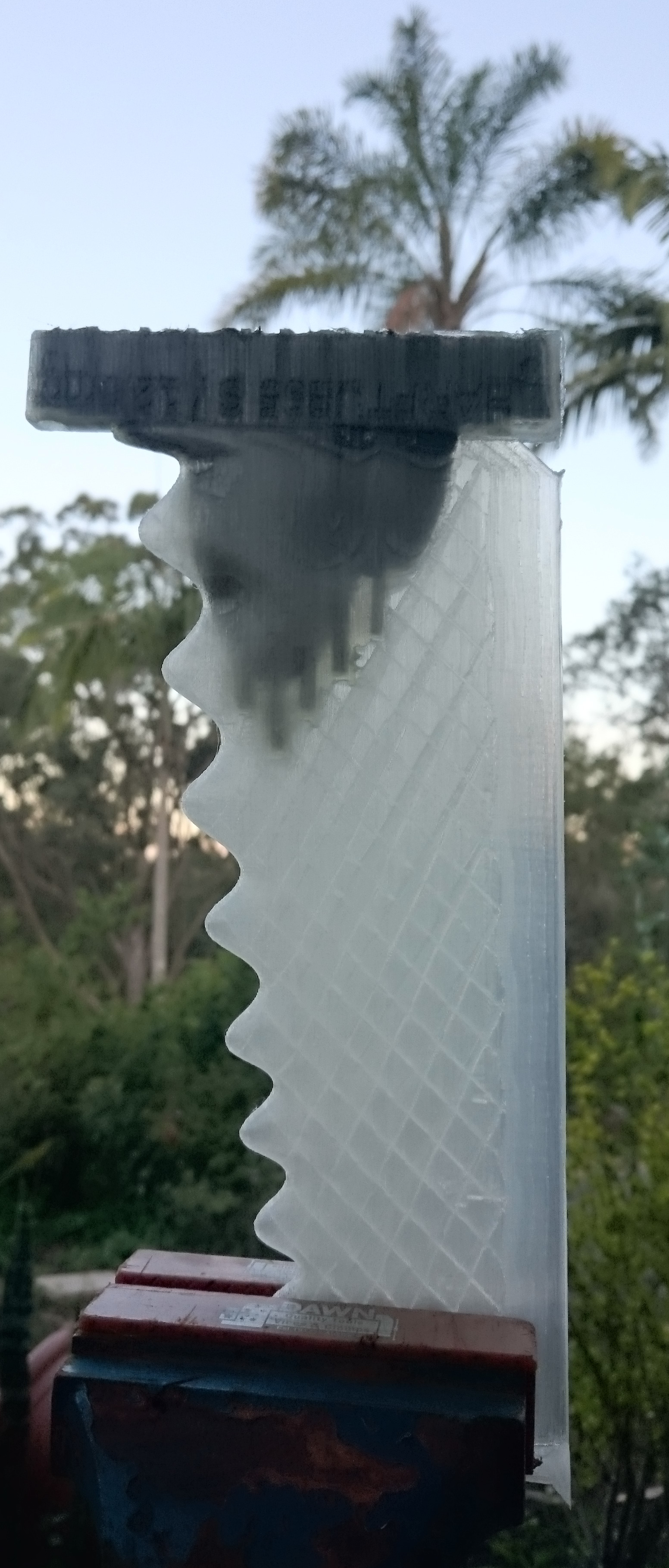
I’m trying hard not to take that transparent fin surfing before the resin has had a few days to fully cure.
.
The carbon rods are probably not needed, maybe they even make the fin weaker, because it destroys the even curve of the filled space and introduces focal points for cracks to start. I have changed the file since then and will fill a few fins without carbon rods, just epoxy and silk.
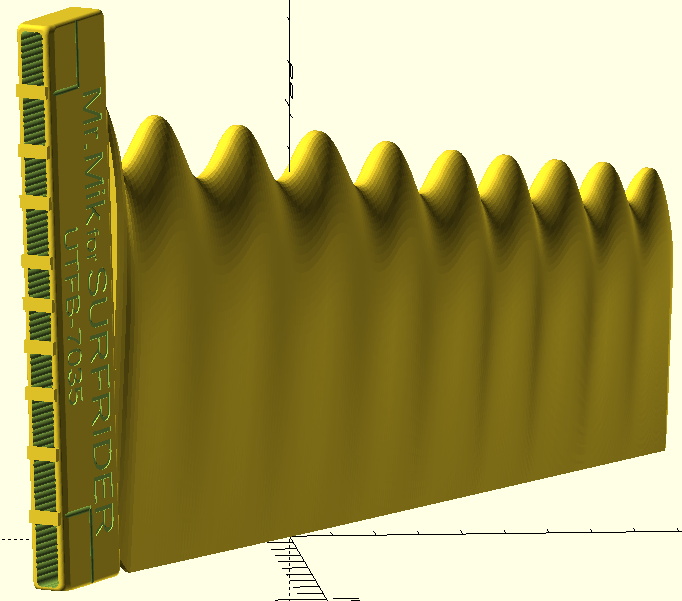
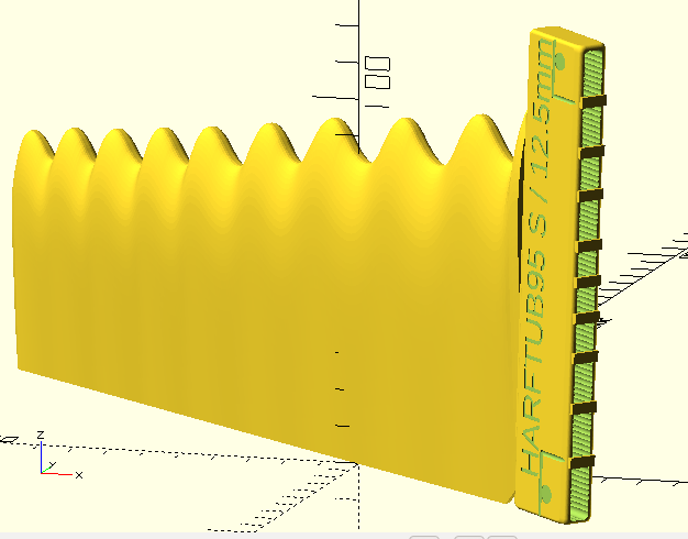
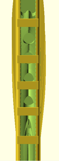
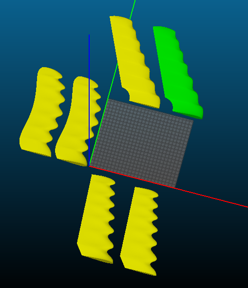
The next stage of figuring out what works best:
3 HARFTUB95 fins with hollow space for resin / fiber filling.
These are all printed solid except for the hollow space.
.
The transparent fin with carbon UTFB shown in the previous post does actually float, so later on I might be able to make all fins lighter by printing them with infill.
But, the transparent fin also soaks up water through the tips of the tubercles and will not float for long, but I have changed print settings to hopefully cure that problem. If not, then a resin or paint coat might fix the leaking issue, but that’s only worth the effort when the fin is fully developed and known to be a great performer.
Using other non-transparent filaments also seems to produce a much more watertight fin and that’s an option for later on as well.
.
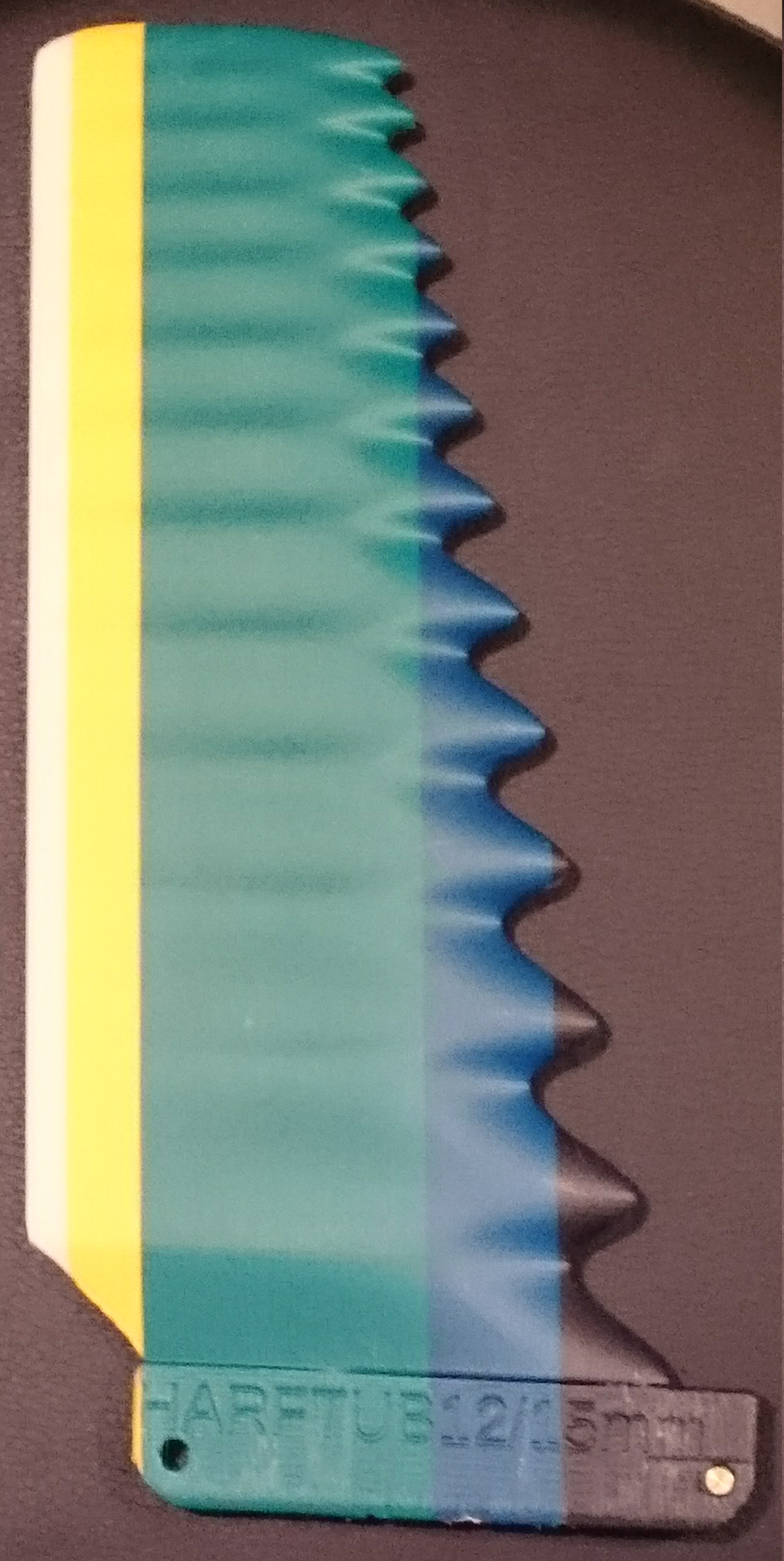
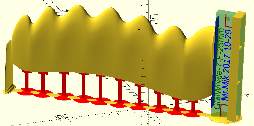
The three fins in the screenshot are identical except for their thickness distribution.
The one on the left is 12.5mm at the base, and tapers gradually toward the tip. It’s the same as the one wrcsixeight (and myself) likes so much, except for higher resolution rendering.
The fin in the middle has a flange 25mm wide and is 12.5mm thick in the central area.
The fin on the right carries the 12.5mm base thickness as far as possible towards the tip.
.
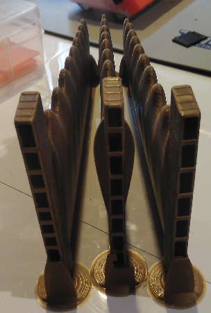
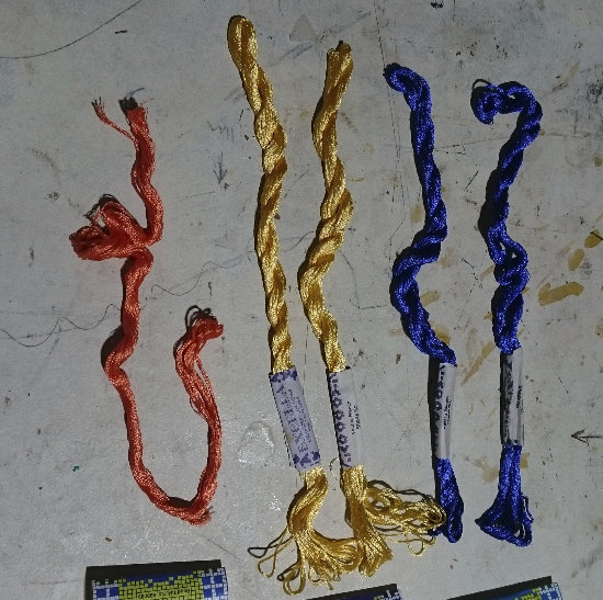
The material used to fill the fin’s UTFB is West Epoxy 105+207, and carbon fibres cut into about 3cm long pieces. I chopped up a roll of carbon tape, about 7 cm wide, I think it’s what they use for deck / rail reinforcement on anorexic thrusters, so the side fins don’t snap the board. I cut it into pieces and then kneaded it all into a matted, felted mass by hand, then stuffing it into the UTFB. The carbon rods really get in the way during this fiddly exercise. I’ll do it differently next time.
You can also see in the photo with the three golden fins that I have gradually reduced the number of stabilisers designed to keep the tab at the correct width. I over-engineered the first one, I think.
.
It’s important the tab stays just the right width, because that is the best part of the UTFB7065 : Total simplicity of the fin retaining mechanism. Elegant solution, I hope.
Simply slide the for roll pin into the fin box to the right position, then push down. Holds rock-solid in my fin boxes. With purely PLA printed fin, the for roll pin snaps off when doing this.
The one in the middle
I’m a total beginner at 3D printing. I print in PLA on a Makerbot and the thing is far too weak. Maybe it’s the direction of the layers. I wonder how you join the base to the fin in 3D software.
Anyway,
So you print the fin, press it into clay and then use that as a mold rather than 3D printing a mold directly as even casting resin would melt the plastic so laminating resin definately would. You then make it hollow by doing the fin in 2 halves and reinforce with some carbon strands. That’s then vacuum bagged.
In another fin you 3D print a base separately with a small kind of fin like thing and then, using a mold, cast the fin only in that base/fin thing and reinforce that with carbon rods.
Seems fun. Will have to give it a go
You must have read through the threads a bit too diagonally.
I learned a lot in the last year, and while I have indeed used some or most of the techniques you mention, I do no longer use them.
.
I 3D print the entire fin directly, using PLA. I found that PLA is one of the mechanically stronger materials, contrary to the mantra that most 3D printers keep repeating.
.
The only downside of the PLA material I have found so far is that it softens too soon in very hot conditions, like in a car parked in the sun. The fins will be OK if kept under other things low down in the car, but they would soon look like they were made by Salvador Daly if they were left on the dashboard in the sun.
To combine foil to base, I usually make them separately and bring them both into OpenSCAD as STL files. I leave the foil at 0,0,0 and move the base to suit.
This can also be done in Meshmixer and other more familiar 3D softwares.
Since the foil has a constant 0,0,0 and size (meters), doing this in OpenSCAD allows you to do a ‘saveas’ and swap in a new base or foil easily.
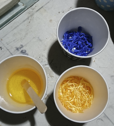
The surfboard repair stands are coming in handy again, a perfect fit for the fins to make filling easier.
28ml resin and 4.5 skeins of silk thread fill the UTFB.
It was a messy affair though.

A few new challenges have joined the lineup of projects.
These fins can all be printed on the Prusa i3MK2, but I need to do some re-designing of the hollow parts for the UTFB, and a lot of support system tweaks will be required for the GullWhale-7 fin and the DeaWeeder fin.
Can’t wait to take them surfing…
The 9.5 turbucle fin is definitely a favorite of mine. They way it will so happily change direction, and stall with no weirdness, is a bit mind boggling. So responsive and predictable. Easily the best overall fin I have used in my longboards, though the wingletted wavegrinder WG2 is noticebly faster and my choice when the surf is tiny or gutless.
On bigger days I when throwing everything I could into a bottom turn with harftub9.5, i was finding the board coming around quicker than anticipated and not getting to the opposite rail in time and getting stuck in the lip. Something that can be learned, but I think the Deweeder fin would extend that bottom turn, and hopefully shed any grass and kelp. It was strange having the board come around some much faster as it does not have much curve or rocker in that pintail.
While the seagrass/ kelp catching proclivities are a bit of a pain, unless it is a huge amount trailing the fin, if more or less feels like my traditional raked fins when dragging something.
Eager to try the 7 turbucle versions, though I still have several other higher turbucle versions I have not yet tried.
I feel honored to be a test pilot on these fins, and pretty much am done with the traditional shaped fins in my longboards. I don’t care if they don’t look right, or cause people to stare and comment and sneer. Honestly most comments are ‘cool fin’ but some older guys seem to have some sort of derisive comment lined up.
The fins with fewer tubercles are ‘growing on me’. I was convinced for a while that more small tubs should be better, because of some research papers I read diagonally. Something about smaller tubs reducing the drag penalty over a straight leading edge fin, while maintaining the delayed staff characteristics. But I never really bothered to understand how they defined ‘small’ and ‘large’ tubs.
Having stared at the HARFTUB65 for a lot of time during the design process, even the HARFTUB95 looks somewhat crowded to me now.
If fewer tubs turn out to be better, that would be great news, because finishing the fins is so much easier than finishing the ones with many small tubs. With few large tubs, sanding and resin coating and polishing is much easier, and the sea weed catching problem could be reduced. Sanding and polishing between the distal tubs of a HARFTUB15 or 20 is next to impossible.
The first print of the HARFTUB65 should finish soon, it has a 9hopefully) much improved system to keep the UTFB dimensionally stable while allowing easy filling with resin / fibre mix.
Well my experience with the harftub 20 was enlightening, in that a fin with the same overall profile and displacement and foil, could feel so incredibly different, and not in a good way.
9 or 9.5 turbucles feels incredible though. Got to find the sweet spot, as it is hard to believe that 9.5 is the magic number and you nailed it on the first try, but it is not impossible to believe.
The turbucled gull wing fin with the concave foil also goes nicely too, but is not as fast nor as loose as the harftub9.5 , but does feel very nice on longer cutbacks when not putting everything into it, and sometimes in the flats, in trim, trying to make it around a section, taps into something below for a bit of the burst of speed like the WG2 and the WG2 clone can routinely tap. I’ve not tried the convex foiled turbucled and non turbucled version you sent.
I have epoxy sanded glossed both harftub 9.5’s and the WG2 clone and white gullwing in addition to fin tab and roll pin reinforcements, but all the other fins I just sanded down the ridges about 75% as kelp/grass seems to stick to them like velcro. Sanding the 20 turbucles to 75% less ridging took forever, so if fewer than 9.5 is better than more, performance wise, then win win.
The support system for the HARFTUB65 fins was easy and I have printed a couple while working on the GullWhale-7 support system.
I also made several improvements to the filling helper box and roughed up the surface of the hollow space for the epoxy cast, to improve the strength of the bond.
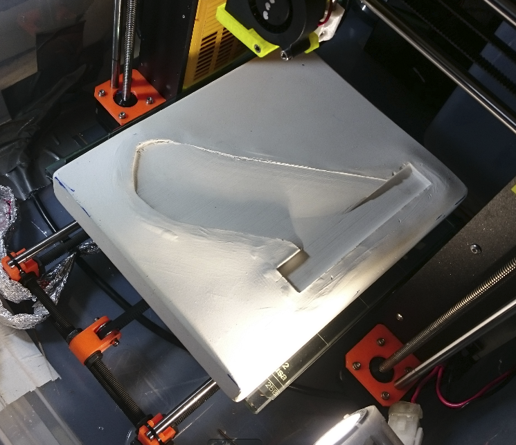
Finally a good use for one of the UTFB-mould prototypes: Extra weigth on a toughened glass plate.
.
Heating the print bed to 100C (not sure if that is the optimal temperature) with a toughened glass plate and extra weight on top levels the PEI sheet bubbles that form because of the warping forces in these large prints.
share some files anyone? just rename the attachment or could use google drive, or mega.nz