lawless,those are the F3 adapters. They come with 6 degrees of cant built in. You can’t secure an FCS fin just by dropping them into a Futures box, though. It needs a screw somewhere.
Would this be of interest to anyone? FCS fin base which you can add your wooden fin blank to and then foil.
Fin blank could be in two halves with appropriate routing, one piece with a slot or glued on pieces of suitable thickness in any configuration you desire.
https://swaylocks7stage.s3.us-east-2.amazonaws.com/s3fs-public/FCSFinBase_1.JPG
Hi RDM-
I think that is a useful design, and could also be useful with a large single tab for the systems with a full length slot like Probox, Ausfinco, etc…
-J
Yep. They would be easy enough to do - as well as a Futures version.
This has been uploaded to thingiverse and sanded will have a link on his website soon. I have made two versions - one with a 3.2mm (1/8") fin support tab and the other with a 4mm.
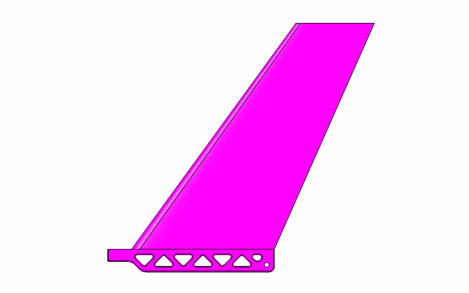
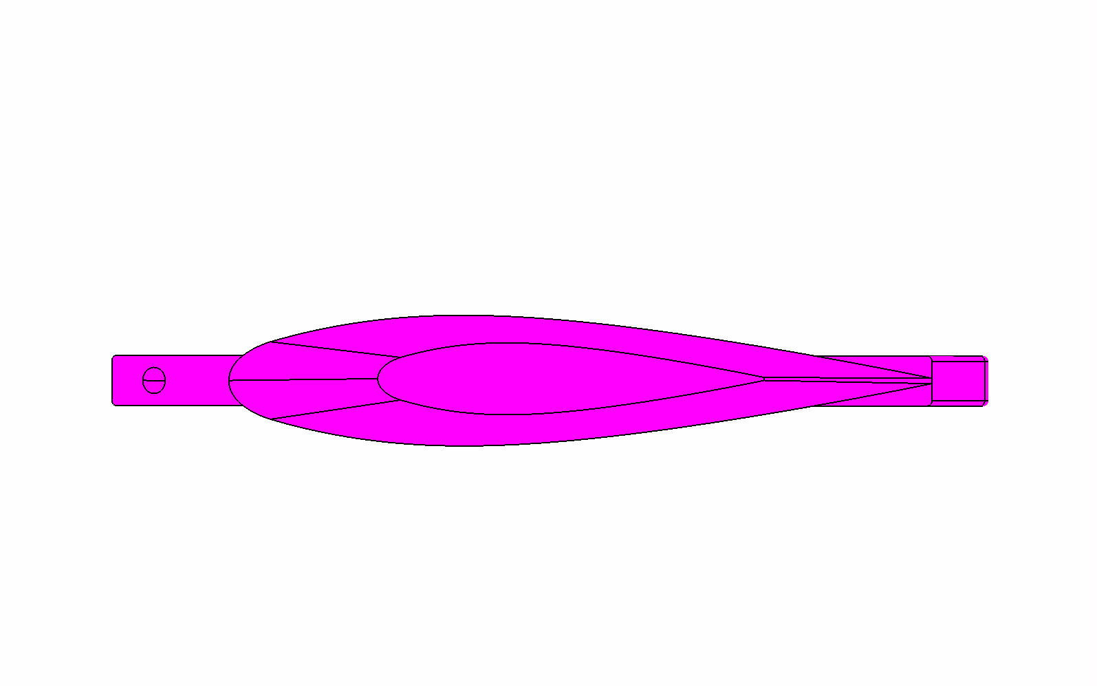
237.5 mm (9 1/3") fin height (not including fin base) with a 16% thickness to chord length ratio (24 mm thick at base of the thickest part of the foiled fin surface). Fin is hollow to reduce weight and cost (with one supporting internal rib).
Top end of fin is solid material for the first 20 mm to allow hand reshaping of this area if desired.
You can download the file from here if you want to 3D print it. Surfboard Fin - Raked Conning Tower Design by CrapolaDesign - Thingiverse
I hope to get the finfoil program running and be able to create and upload some more conventional designs in the future.

Good work definately!
Have you seen this?
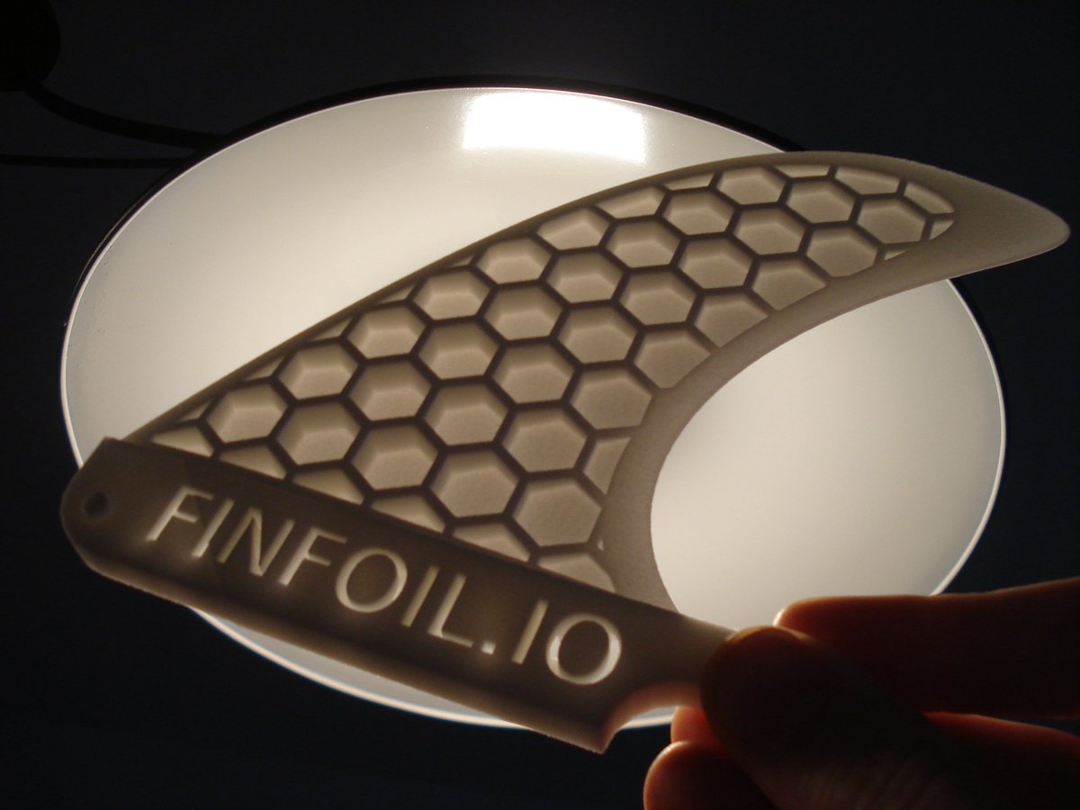
I have scripts to automatically hollow fins designed with finFoil using a hexagonal structure.
However, due to the dissapointing lack of donations I chose to focus my free time on other projects that get more donations, so I can’t justify my time to make this available through the web.
However, for the true swaylocks finFoil supporters (you should know yourself if you are one ![]() ) I’m always happy to generate a hollowed STL for your design and add a base too, just contact me through PM.
) I’m always happy to generate a hollowed STL for your design and add a base too, just contact me through PM.
BTW here you can watch the fin in 3D: http://finfoil.io/s/r/j63wz
I can’t see your FCS base RDM?!?!?!
The FCS base design should be here Surfboard Fin Box Base FCS by CrapolaDesign - Thingiverse
Let me know if that doesn’t work.
Great work!
Any hints what design software to use to have a crack at it?
I want to make a negative of a fin base, a split mould, to allow accurate reproduction using materials not available for 3d printing. In other words, use cheap materials to print a mould, then cast or laminate into the mould.
OpenScad is a bit tricky, but I think I’ll give it a go as it’s free and works in Linux.
Hey MrMik.
I can easily give you a CAD model of negative of just a fin base, given that I already have the positive. But if you want a negative of the complete fin then it would be best to contact Hans (on this thread) to see if he is able to help, or download his software to model the fin itself. I believe he also will have a CAD model of a standard fin base. OpenScad will easily build you a fin base negative but will not be suitable for free form surfacing of the fin itself. Only Hans and his software will be able to help you, unless you have someone who has and can run ALIAS, ICEMSURF, MAYA, etc.
If Hans’ software (finfoil) can export a STEP or IGES file then I can add it to my model of the fin base and create CAD model of a split negative mould for you.
Rohan, You’re always generous with your time to help others.
Thanks for your help with previous projects and future ones !
Hey Brett. I have had many on this site be generous with their time in helping me out. Would be a little rude to not in turn repond generously to others here. What goes around comes around and a few hours here and there will hardly cause me any great trauma.
2 STL files (1 from finFoil) and 20 lines of code in OpenSCAD. Once you get the first one into OpenSCAD, the code is recycleable into the 2nd, 3rd,…
Let me kow if I can help, I wouldn’t have gotten this far without other people helping me either.

Thanks RDM, much appreciated.
For the moment, I’m just trying to make a fin base with a ‘spine’ to which the eventual fin material will attach. Similar to the one in the photo. Eventually I might try to make an entire fin ‘virtually’, but for now I’m just struggling with getting the fin base right when sanding it by hand. I find it much easier to hand-shape the flowing curves of the fin than the straight lines of the base.

Jrandy, that looks great!
Can you share the code for OpenScad?
PM sent.
MrMik, PM sent.
I figured out the very basics of OpenScad, with the help of youtube: https://www.youtube.com/watch?v=eq5ObNeiAUw
Result: Not much yet, but promising.
I’ve cobbled together an STL file of my ToughFinBase_1.3…I guess it’s what I need to send to a 3D-printer. It looks like this (and I don’t understand one bit of it!):
solid OpenSCAD_Model
  facet normal 0.994522 0.104529 0
   blah blah blah blah blah....
lots more blah blah blah...
finishing with:
      vertex -70 40 -4.5
    endloop
  endfacet
endsolid OpenSCAD_Model
And the instructions for the OpenScad file (that was exported into the above STL file) looks like this:
**translate([-20,38,0])
cylinder(h=9,r=50, center=true);
cube([225,24,9], center=true);
translate([-20,15,0]) cube([100,50,9], center=true);**
Those four lines above I had to actually type in myself, to create the shape shown in the attached screen shot below.
Next step will be to create the virtual mould, then use the ‘difference’ command to remove the ToughFinBase shape from the virtual mould, and export it to a STL file again.
