Build your own fin -"3D printable single fin base"

You are on the right track.

The difference command will be first

The mould base and any translate command related to it will come second, making it the ‘positive’ for the difference command

Then the entities to be molded will be third, becoming the negatives for the difference command

An external STL can also be an object by using the import command

I need some help with details.

Problem 1: How can I print out a true to scale (approximately) 2d page of my attempt to make a Tough fin Base? I want to lay it on top of actual fins and mould to check that it will fit well.

Problem 2: How can I make a cube (well, that’s probably the wrong term. It’s more like a wedge) that is a little thinner on one end compared to the other? I want the fin base to be 8.9mm at the very bottom, and 9.1mm at it’s top. I suppose I have to remove a slither of a triangle from the cube on each side, or is there an easier way?

Thanks for all the help with this!

The pictures show the OpenScad view and a real prototype Tough Fin Base on top of the Dummy Fin Base on top of a fin that they are supposed to fit into.

The code for the OpenScad shape is:

//dimensions wanted: 200mm long; 24mm high; 8.9mm wide at bottom, 9.1mm wide at top of tab; centre circle 93mm from front of tab;

translate([93,50,0.05])cylinder(h=8.9,r=50);

cube([200,24,9]);

translate([43,0,0.05])cube([100,50,8.9]);

translate([75,100,0.05])cylinder(h=8.9,r=30);

translate([85,130,0.05])cylinder(h=8.9,r=21);


Problem 1:

In OpenSCAD: Set the view, export an image, bring the image into a softare that will let you resize the image to 1:1. Use the 24mm or 200mm dimension as a check.

Problem 2:

 //tapered fin base

 linear_extrude(height = 200, center = true,twist = 0)

 polygon(points=[[.05,0],[8.95,0],[9.1,24],[0,24]])


Thanks, jrandy!

And 'cause I’ve practiced a little bit, I managed to spot the problem in the code: There is a missing " ; " at the end.

Other errors (when there is an incorrect character in the string) are automatically highlighted, but a missing character seems to pose a problem. You need to spot it yourself or nothing will work.

I like the ‘linear_extrude’ function. Very neat solution. Fun to play with the ‘twist’ option.

This whole 3d designing business is really quite simple. Anyone lurking and worried about it should really just give it a go.

Install OpenScad (apparently available for the common operating systems), then copy + paste text like the bits shown here into the area on the left side of the OpenScad screen. Then,  change a few numbers here and there and watch what changes when you click on the ‘Render’ button.  You’ll soon get the hang of how easy it really is.

Particularly if you have friendly helpers like on Swaylocks!


Thanks again!


I found another way to print a 2d image ( by reading the manual at OpenSCAD User Manual/Using the 2D Subsystem - Wikibooks, open books for an open world ):


projection(cut=false){

translate([93,50,0.05])cylinder(h=8.9,r=50);

cube([200,24,9]);

//translate([-20,15,0])

translate([43,0,0.05])cube([100,50,8.9]);

//translate([-138,-35,-30])cube([275,140,34]);

translate([75,100,0.05])cylinder(h=8.9,r=30);

translate([85,130,0.05])cylinder(h=8.9,r=21);}

Then File>Export>Export as DXF…

The DXF file can be opened with another free Open Source program named ‘LibreCad’.

With a very small bit of fiddling, Librecad printed the outline of the Tough Fin Base in its actual size. The only problem was that the printout was initially crossing into the non-printable margins of the page, but in the print view you can drag around the page so the design is located in the middle, and then all is good.

The photo shows the advantage of ‘measuring twice and printing once’, so to say.


OpenSCAD finbases can be found here: https://github.com/hrobeers/finbases

**The license requires you credit the finFoil project when sharing! (**http://www.finfoil.io/)

Thanks Hans, I’ll add mine if I ever manage to finish it.

My current hurdle with OpenSCAD is this: How can I zoom in on the detail of any part of the design that is not located at the centre of XYZ crosshair? It always zooms in on the centre.


The benefits of 2D printing:

I have the rough outline for the Tough Fin Base ready. Printing it (repeatedly during development) 2 dimensionally allowed to adjust it, so it will probably fit a variety of fin moulds.

The WaveGrinder fin will need some grinding to make it fit, but for the various Gull-Wing and Gull-Whale  fins, and my own hand shaped adaptation of them, the same TFB should fit.

It’s a bit tedious to do the first time around, but you can build a library or virtual parts and combine them over and over for use in later projects. So the effort is not wasted.

Here is the code for the OpenSCAD file behind the paper-cutout in the photos:

‘ToughFinBase_3.4.8.scad’:

  1. projection(cut=false){
  2. rotate([90,0,0]){
  3. linear_extrude (height = 200, centre = false, twist = 0)
  4. polygon(points=[[0,0.05],[0,8.95],[24,9],[24,0]]);
  5.  
  6. translate([40,8.95,93])
  7. rotate([90,90,0]){
  8. cylinder(h=8.9,r=40);}
  9. translate([80,8.95,80])
  10. rotate([90,90,0]){
  11. cylinder(h=8.9,r=35);}
  12. translate([100,8.95,70])
  13. rotate([90,90,0]){
  14. cylinder(h=8.9,r=35);}
  15. translate([130,8.95,60])
  16. rotate([90,90,0]){
  17. cylinder(h=8.9,r=33);}
  18. translate([160,8.95,60])
  19. rotate([90,90,0]){
  20. cylinder(h=8.9,r=28);}
  21. translate([180,8.95,75])
  22. rotate([90,90,0]){
  23. cylinder(h=8.9,r=25);}}}

Photos show the paper 2D shape of the ToughFinBase_3.4.8.dxf file overlaying these fins:

‘Turmfalke’

E168Gullwing-Fin

E168Gull-Whale-Fin

Wavegrinder fin (encased in latex)

Staight Tip Gullwing-fin (encased in latex)

Standard Gullwing-fin (encased in latex)

Extended tip Gullwing-fin


What are the properties of ABS and PLA filament when used with epoxy resin or polyester resin?

If I buy a printer using either ABS or PLA filament cartridges, will I be able to cast or layer fibreglass and resin into a printed mould and get it back out, or would it bond together?

MrMik- What if you traced all 6 fins onto one piece of paper and figured out a hybrid DFB/TFB that is truely one size fits all? Then foil it, add some generous fillets and some holes for interlocking to the overmolded fin. It would be a shame to make a nice fin base mold only to have multiple grinding schemes to make the molded piece work for the entire range of your nice molds.

That’s pretty much what I’m trying to do, but I think I might make a mould that produces a TFB that is as strong as possible, and then I make the space in the mould smaller when I make a TFB for a smaller fin.

I’m thinking of laminating carbon fibre cloth into each half of the TFB split mould, then put the halves together with a little bit of excess resin to be squeezed out. I might even print the TFB rather than a mould for it, and then make a plaster mould following Finfoils fin casting method.

The exact shape of the spine and fillets is not important, as long as it is strong enough to stop the fin from snapping off during all normal surfing conditions.

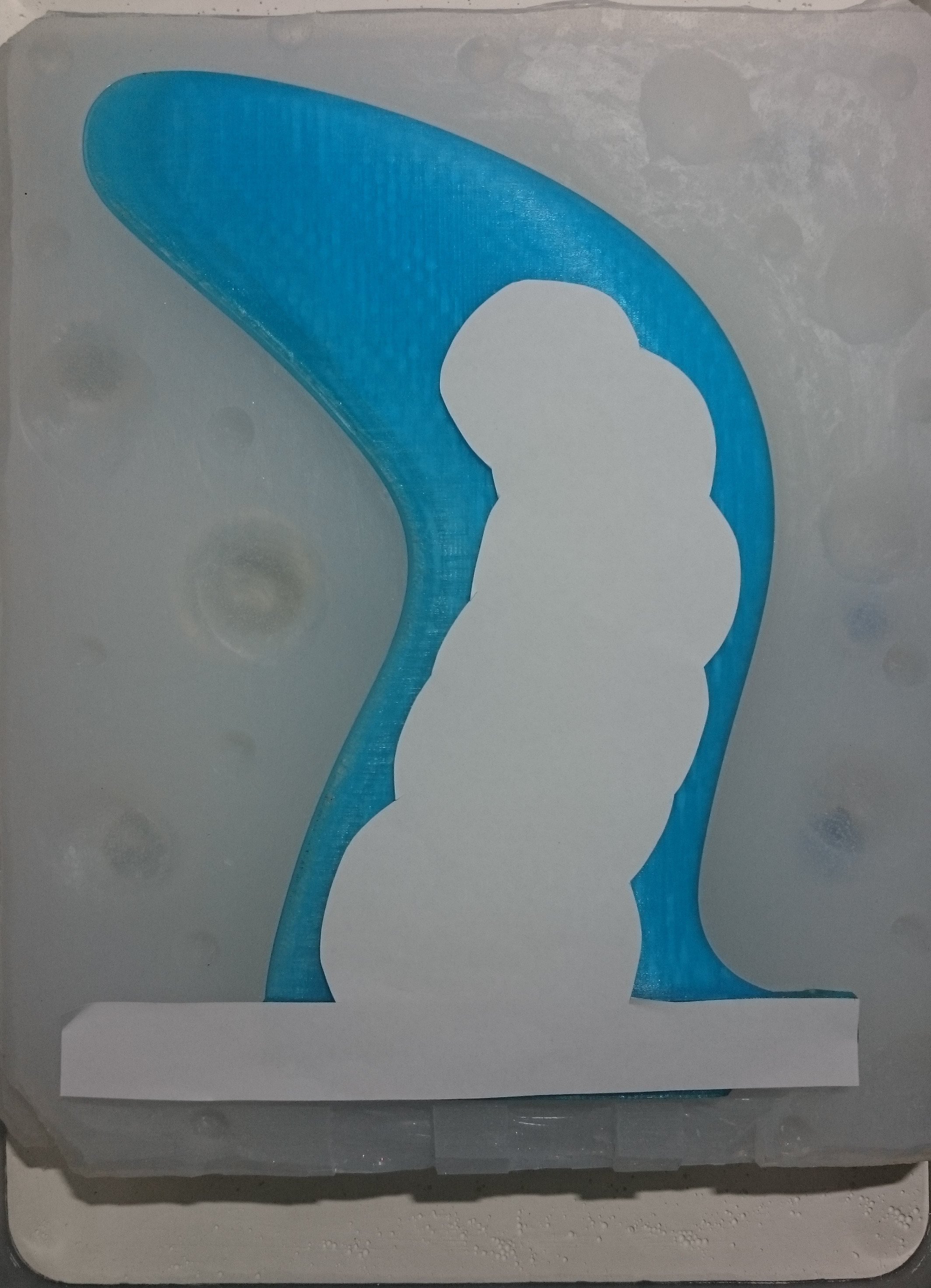
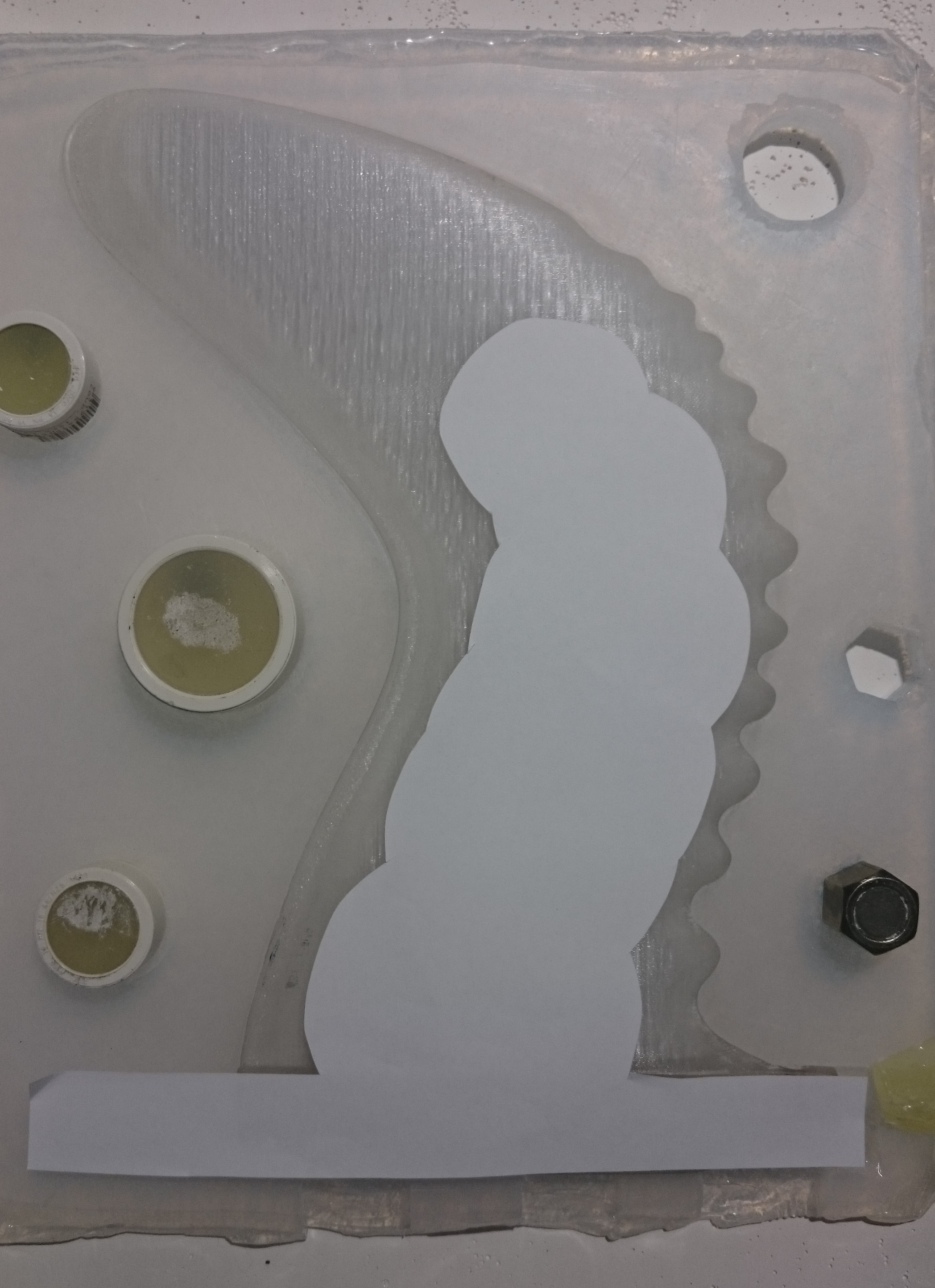
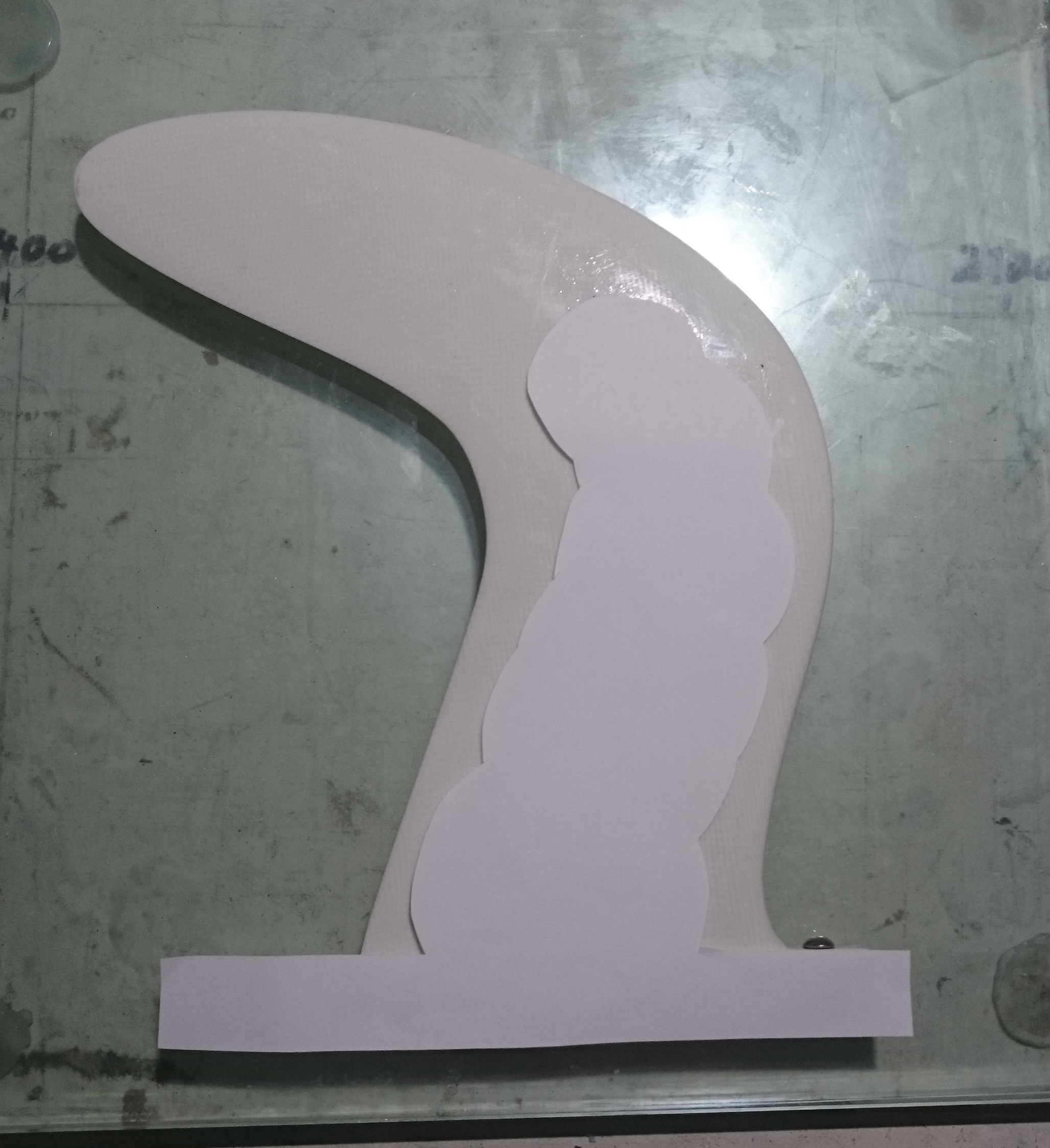
My minimalistic approach to the 3D Tough Fin Base design: One extruded polygon and the rest are all cylinders.

Unfortunately it turns out to be quite expensive to buy a suitable 3D printer, and online printing is surprisingly expensive, too.

It could cost around AU$200.- to print both halves of the split mould, and a suitable printer would cost AU$1300.- .

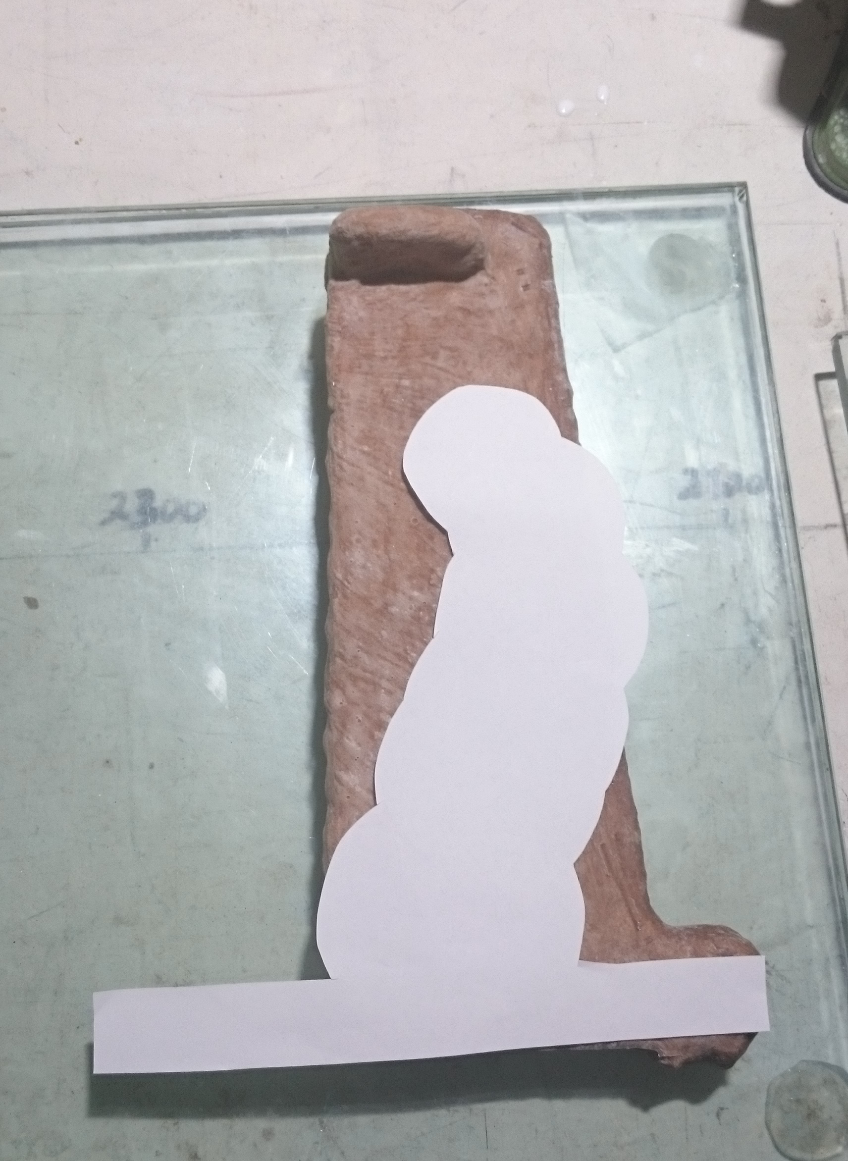
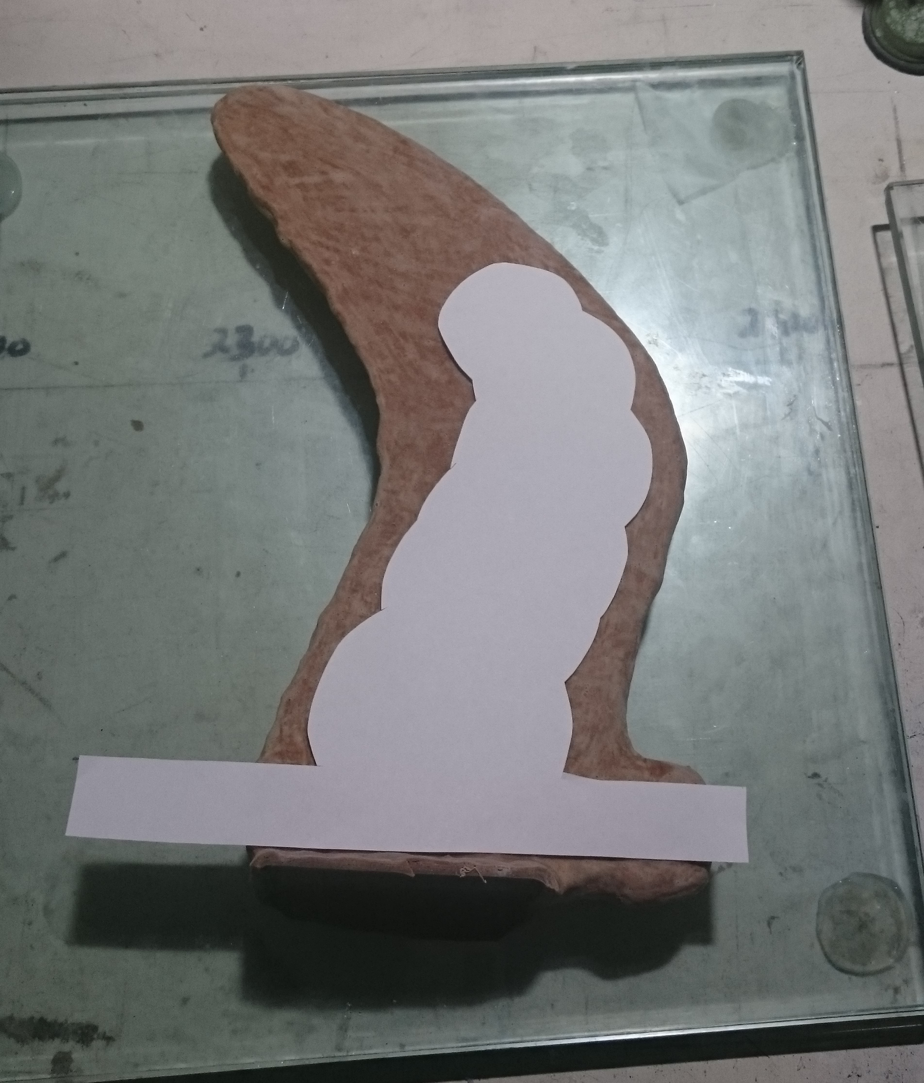
For now, I’ll try a bit longer to manufacture a near perfect TFB by hand. But it’s only a matter of time before I will cave in and buy a printer.


//194mm x 194mm to allow 3mm thick mould walls on 200 x 200 printer.


difference() {


color("blue",0.1)

translate([-3,-100,-3])

cube([200,200,7.5]); centre=true;


color("red",0.25)


translate([0,97,0]){

rotate([90,0,0]){

linear_extrude (height = 194, centre = false, twist = 0)
    
polygon(points=[[0,0.05],[0,8.95],[24,9],[24,0]]);

translate([40,8.95,93])
rotate([90,90,0]){
cylinder(h=8.9,r=40);}

translate([80,8.95,80])
rotate([90,90,0]){
cylinder(h=8.9,r=35);}

translate([100,8.95,70])
rotate([90,90,0]){
cylinder(h=8.9,r=35);}

translate([130,8.95,60])
rotate([90,90,0]){
cylinder(h=8.9,r=33);}

translate([160,8.95,60])
rotate([90,90,0]){
cylinder(h=8.9,r=28);}

translate([169,8.95,68])
rotate([90,90,0]){
cylinder(h=8.9,r=25);}

translate([177,8.95,58])
rotate([90,90,0]){
cylinder(h=8.9,r=15);}

translate([153,8.95,43])
rotate([90,90,0]){
cylinder(h=8.9,r=15);}

translate([153,8.95,75])
rotate([90,90,0]){
cylinder(h=8.9,r=15);}

translate([146,8.95,41])
rotate([90,90,0]){
cylinder(h=8.9,r=15);}

translate([110,8.95,46])
rotate([90,90,0]){
cylinder(h=8.9,r=15);}

translate([120,8.95,83])
rotate([90,90,0]){
cylinder(h=8.9,r=15);}

translate([77,8.95,58])
rotate([90,90,0]){
cylinder(h=8.9,r=15);}

translate([57,8.95,66])
rotate([90,90,0]){
cylinder(h=8.9,r=15);}

translate([70,8.95,106])
rotate([90,90,0]){
cylinder(h=8.9,r=15);}

translate([26,8.95,66])
rotate([90,90,0]){
cylinder(h=8.9,r=15);}

translate([26,8.95,124])
rotate([90,90,0]){
cylinder(h=8.9,r=15);}

}
}
}


A question about printing fins: Must the fin be printed standing straight?

Or could the fin be printed in a ‘lying on it’s side’ position?

Most 3D printers do not have enough height to print a large single fin if it needs to stand upright.

I have an idea to combine a few techniques for a hybrid lamination / 3D printing technique for fins.

A) Print a mould for a tough fin base (TFB). Make very strong but light carbon fibre + epoxy laminated TFB’s in the mould.

B) Print a fin top that fits almost exactly on top of the TFB, like a crown on a prepared tooth, with just enough space left for a bit of glue. No undercuts, but recesses that fill with glue and then permanently bond the fin top to the TFB.

This technique would get around a number of problems with fin printing.

Problem 1: The fins tend to snap off because even polycarbonate is not strong enough for large single fins. Polycarbonate printers need to have a 300degC hotend and are more expensive.

Problem 1b: For printing a complete large fin in one material, you can only use polycarbonate (or maybe carbon fibre?) filament. But if you use a TFB to give structural strength to the fin, you can use materials that are easier to print (ABS or PLA), and so you could use a much cheaper printer. You could also print a flexible or rubbery fin to fit on the TFB. Or several parts, e.g. a trailing edge that does not cut you and is more flexible than the rest of the fin.

Problem 2: The fins are too big for ‘cheaper’ printers. With a 2-part fin, the 24mm from the fin base make them small enough to be printed on some very good but not extremely expensive printers. But, only if they can be printed lying down.

Does anyone here know if they could be printed lying down, maybe with a dual print head using PVA as temporary structural support, or some added ‘posts’ that will get sanded off after printing?

See photo for some print bed comparisons of potential printer candidates.


I jumped right in and ordered a 3D printer kit.

Apparently ‘skirts’ should allow me to print a fin lying on its side.

This printer seems by far the best value for money to me (but there are so many it’s hard to even get a good overview):

http://shop.prusa3d.com/en/3d-printers/59-original-prusa-i3-mk2-kit.html


This hurdle was just taken by accident…(after many deliberate attempts to do it, and to yahoogle it etc…)

To zoom in on anything other than the centre of the xyz crosshairs in OpenScad: Right click and hold, then drag the entire view around. Then, you will zoom in on the new centre of the view when scrolling the mouse wheel.

To turn this back off, double-left-click on the centre of the xyz crosshairs.

Universal Tough Fin Base - at least I’m hopeful.

The UTFB file is ready for printing when the printer arrives (and once I managed to assemble the kit).

I’ll print the actual UTFB first, and then make adjustments as required before turning it into a mould for laminating carbon / epoxy UTFB’s.

If you want to have a play with it in OpenSCAD, here is the code:


// UNTESTED - NOT YET PRINTED.

// Universal Tough Fin Tab  UTFB_3.9.scad

// Code for use in OpenSCAD

// $fn=XYZ; sets the level of detail. Above 35 causes many computer crashes when rotating the model.

$fn=100;


// The following command produces the 2D output when the “//” are removed.

//projection(cut=false){


// To rotate everything; required to allow 2D printing of outline:

rotate([90,0,0]){


// This makes the fin base green in Preview:

color(“green”,0.25){


// Minkowski sum three times to round the base edges:

  minkowski(){

    minkowski(){

        minkowski(){


// Linear Extrude length of the fin base reduced to compensate for elongation due to Minkowski sum:

  linear_extrude (height = 146, centre = false, twist = 0)


// Polygon points brought closer together to compensate for enlargement due to Minkowski sum. Without Minkowski sum use: [0,0.05],[0,8.95],[24,9],[24,0].

// Might need to change it to 9mm bottom and 9.1mm top for use with ball spring plungers for snap-in fins.

polygon(points=[[0,3.05],[0,6.95],[19,7],[19,3]]);

// 3 cylinders each rotated differently to round off the edges with the Minkowski Sum function:

    cylinder(r=1,h=1); }

    rotate([0,90,0])

        cylinder(r=1,h=1); }

    rotate([90,0,0])

        cylinder(r=1,h=1); }


// defines end of GREEN color for base:  

    }


// This makes the ‘hull’ red in Preview:

color(“red”, 0.5){


// The Hull function creates the spine on the fin base, by connecting modified spheres and automatically tapering the edges:   

hull(){


// This moves the entire ‘hull’ to the right position on the fin tab:

translate([0,4.5,69.5]){ 


// Forward + proximal sphere in the hull:

    translate([22.5,0,0]){

    rotate([90,0,0])

resize(newsize=[45,60,9])

sphere(r=10); }

// Central 9mm thick sphere in the hull, to make the 9mm area at the base bigger:

     translate([22.5,0,25]){

    rotate([90,0,0])

resize(newsize=[45,60,9])

sphere(r=10); }

// Aft + proximal sphere in the hull:

    translate([22.5,0,25]){

    rotate([90,0,0])

resize(newsize=[45,60,4])

sphere(r=10); }


// Tip sphere in the hull:

translate([130,0,0]){

rotate([90,0,0])

resize(newsize=[75,30,4])

sphere(r=10); }

}

}

}

}

// End of Code.

Mr Mik, you certainly are a man of perseverance. If the printer works for you, its something a lot of people might buy.

MrMik, congrats on the progression of your OpenSCAD work. That one looks like a winner for printing a 3D mold.

If I understand correctly, good concept.  I like it.

I am illiterate when it comes to CAD.  But I think I am beginning to see what you are after with a TFB.

If I am getting it, I have been thinking about a similar concept using a flat, wood-frame perimeter with the outline shape of the fin – sort of like a picture frame.  In my mind, the fin base/box insert would be easier to make this way.  The frame would be the middle piece/layer with carbon or FG rods and particle re-inforced fill within that flat frame.  Then add one piece of shapable wood sheet on both sides of the flat, middle frame piece (with rod and re-enforced resin fill).  The leading and trailing eadges of the flat middle frame are wood that is readily shapable as well.  Then add a thin shell of FG or Carbon cloth to the shaped fin’s surface.