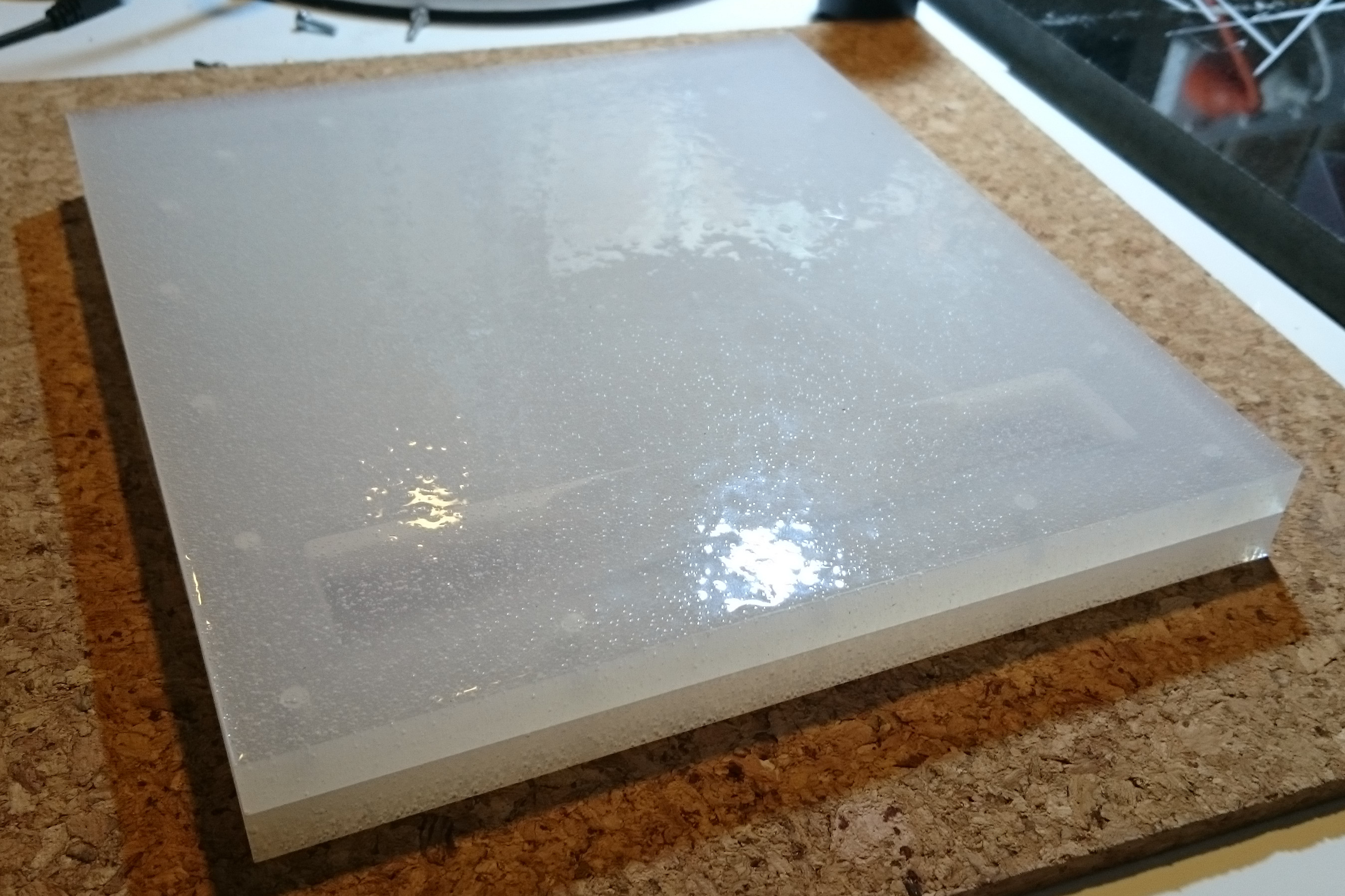
The halves do fit together perfectly. Phew!
It remains to be seen what the exact dimensions will be when I de-mould the first epoxy cast into this mould.
The halves do fit together perfectly. Phew!
It remains to be seen what the exact dimensions will be when I de-mould the first epoxy cast into this mould.
I think I have now figured out how to print a fin. BIGFATGRIN
The general approach seems clear enough. Another decade and I’ll surely will have a prototype to show…Yippeeeeh!
But, just in case I get hit by a big red bus tomorrow, I think I should share in time. So, here goes:
Mik
The UTFB is too fat to fit inside of a fin. So that was a bit of a waste of silicone resin, apart from the lessons learned and the ‘proof of concept’.
The picture shows a screenshot from OpenScad where I have combined the UTFB 24-5 with Peregrin 1-9.
Back to the drawing board, but this time the finFoil drawing board, to make a better shaped UTFB.

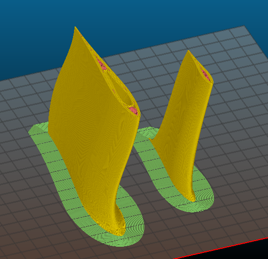
Spiral vase mode does not work. The thin walls warp irregularly and destroy the intended foil.
Ned to print with infill. I hope the warping will not be an issue when a hollow space is left for later insertion of a UTFB. It will be a balancing act between thin + weak UTFB or thin and warping fin shape. But, if the fin is thin and only hollow where the UTFB will go, then the UTFB might force the thin shell into the right shape.
Need to figure out a way to use finFoil to create fin and UTFB well matched to each other.
I made a new core for the Peregrin Fin, using finFoil.
Slic3r is very useful to analyse how the shapes fit , particularly how thick the walls are around the core cavity of the fin.
Theoretically this core should fit, or maybe it is just too large, or maybe I have misjudged and there is an undercut somewhere so it cannot be inserted.
Time will tell. Time to start up the printer and make PLA prototypes.
Then I’ll probably ‘scale’ the insert down by 1% or so until it fits and leaves a bit of room for epoxy glue, virtually insert it into the UTFB mould-mould, print the mould-mould, pour silicone mould halves, then make a carbon+epoxy core.
Once it all works, I’ll print the fin from polycarbonate and then glue the carbon-epoxy UTFB into it.
We’ll see what goes wrong this time…


It’s coming along nicely in the virtual world.

But the printed result is not so great…
Due to stringing inside the void in the fin, the plug does not go in fully. Now it’s stuck good and proper.
However, it’s proof of concept that a fin can be printed on this printer.
I think I will abandon my attempt to make a floating snap-in fin for now, and just make a fin that does not snap off.
I’ll re-design the cavity to make it larger, then make a silicone mould for the fin base, and then fill the mould and fin cavity with resin and carbon fibre. If that works and does not snap off, then I’ll return to experimenting with making it lighter.
I found a way to design the core for the fin: Take a screenshot of the finFoil display, then re-import it into finFoil, then shape the same fin file so it overlays the thickest part of the fin.
Many other small incremental changes to size in various axes were involved. The fin stayed the same, still Peregrine 1.9, but the cavity and the plug for the cavity were modified.
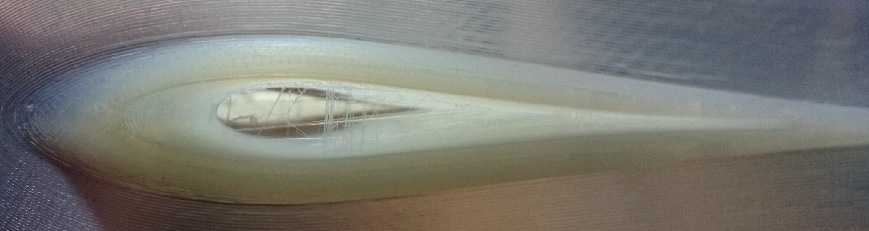
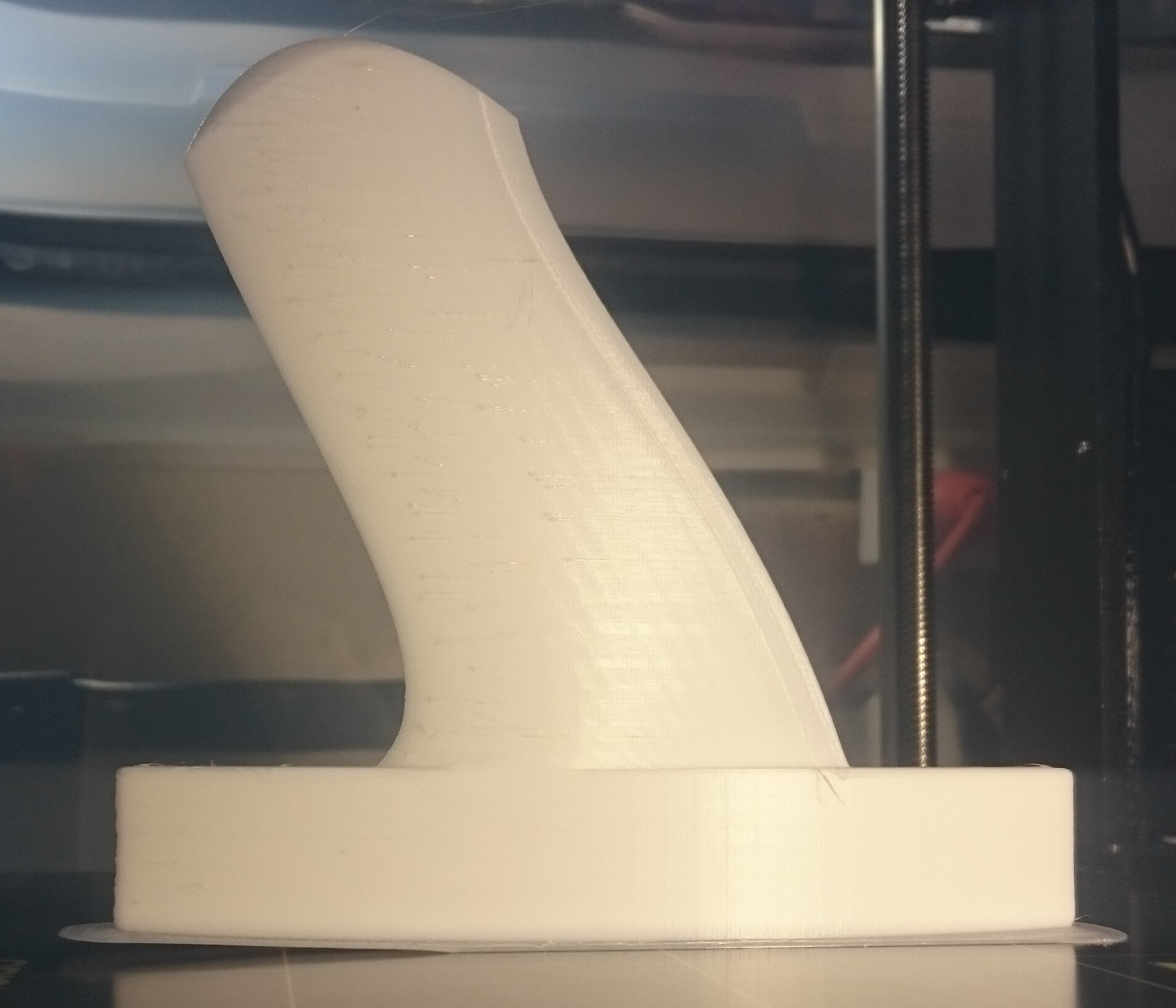
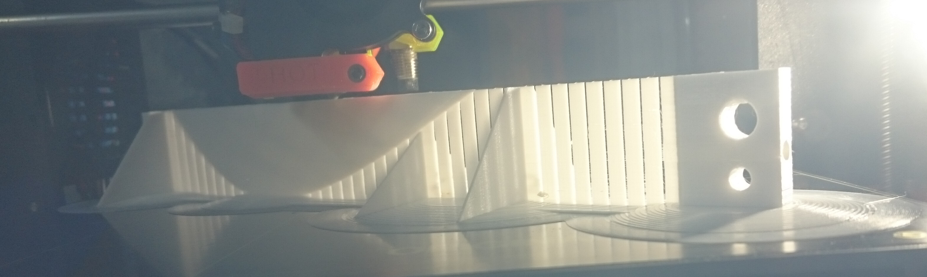
Shown below are photos of the next print of the fin and the (polycarbonate) UTFB with plug - this time it actually goes in and comes back out of the fin!
The backlit photo shows the internal structure of the fin. The cavity is larger than the no-undercut part that the plug fits into. That way, it can be filled with resin for added strength if necessary.
The polycarbonate UTFB warped quite a bit, but only the base. The real UTFB=plug will be manufactured in a silicone mould, from epoxy resin and carbon fibre.
Here is the OpenScad code. Those who have a little experience with it might find it useful.
Send me a pm if you would like me to email a copy of the .stl files required to make it work.
$fn=15;
// Disable the base plate when printing fin without UTFB. The base plate purpose is to get rid of gaps between rounded UTFB tab edges and bottom of plug
//color(“blue”)
// translate([-41.25,-2.5,0])
// cube([77,5,9.1], center=true);
// Insert UTFB here when needed for UTFB printing. Move it to the position marked below when making a fin-only file.
// Making the fin hollow:
difference(){
//Importing the Wanderfalke_1.9 fin file
// Disable next 2 lines to make a file for the plug without the fin (must also move Union of UTFB to right location).
resize([0,200,0], auto=true)
import(“/media/p/Shared_NTFS_2/3D_printing_stuff/finFoils/Wanderfalke_1-9.stl”);
// Insert UTFB here to keep the code in the file when not needed. Move it up to the marked location when making files including the UTFB.
// Union of UTFB to allow importing the entire UTFB-tab into another OpenScad file
translate([-116.385,-22, -4.5])
rotate([0,0,90])
union(){
// To remove the BSP markers by ‘differencing’ the UTFB-Mould from it:
difference(){
// To rotate the UTFB; It was required to allow 2D printing of outline in an earlier development step:
rotate([90,0,0]){
union(){
// This makes the fin base green in Preview:
color(“green”,0.5){
// Minkowski sum three times to round the base edges:
minkowski(){
minkowski(){
minkowski(){
// Linear Extrude length of the fin base is reduced to compensate for elongation due to Minkowski sum. Actual length after Minkowski was 150mm in initial UTFB versions (height=146); reduced to 135mm (height = 131) in Wanderfalke-cored_UTFB_2-3.scad:
linear_extrude (height = 131, centre = false, twist = 0)
// Polygon points brought closer together to compensate for enlargement due to Minkowski sum. Without Minkowski sum use the actual intended size.
// 9.2mm wide fin base with small taper at bottom to ease entry into the fin box.
// Use these dimensions instead for 9.2mm fin base without taper: polygon(points=[[0,2.9],[0,7.1],[19,7.1],[19,2.9]]);
polygon(points=[[0,3.1],[0,6.9],[1.5,7.1],[19,7.1],[19,2.9],[1.5,2.9]]);
// 3 cylinders, each rotated differently, to round off the fin base edges with the Minkowski Sum function:
cylinder(r=1,h=1); }

rotate([0,90,0])
    cylinder(r=1,h=1); }

rotate([90,0,0])
    cylinder(r=1,h=1); }
// defines end of GREEN color for base:
}
}
}
// Cutting out cylinders for ball spring plungers:
// First forward BSP:
// Move cylinder cutout for BSP
translate([7,-10,9.1])
// cylinder for BSP
cylinder(h = 1, r = 0.75, center = true);
// 2nd BSP:
// Move cylinder cutout for BSP
translate([9,-28,9.1])
// cylinder for BSP
cylinder(h = 1, r = 0.75, center = true);
// 3rd
// Move cylinder cutout for BSP
translate([11,-46,9.1])
// cylinder for BSP
cylinder(h = 1, r = 0.75, center = true);
// 4th
// Move cylinder cutout for BSP
translate([13,-64,9.1])
// cylinder for BSP
cylinder(h = 1, r = 0.75
, center = true);
// 5th
// Move cylinder cutout for BSP
translate([13,-82,9.1])
// cylinder for BSP
cylinder(h = 1, r = 0.75, center = true);
// 6th
// Move cylinder cutout for BSP
translate([11,-100,9.1])
// cylinder for BSP
cylinder(h = 1, r = 0.75, center = true);
// 7th
// Move cylinder cutout for BSP
translate([9,-118,9.1])
// cylinder for BSP
cylinder(h = 1, r = 0.75, center = true);
// 8th
// Move cylinder cutout for BSP
translate([7,-136,9.1])
// cylinder for BSP
cylinder(h = 1, r = 0.75, center = true);
}
}
// End of UTFB tab
// Add modified sphere to round the forward tip of the plug
// For plug use: translate([-40,-32,0])
// For core use: translate([-40,-31,0])
// To make a fin to be filled with liquid resin: disable the modified sphere intersection.
//intersection(){
//rotate([0,0,-20])
//translate([-40,-32,0])
//translate([-40,-31,0])
//resize(newsize=[100,250,20])
//sphere(r=1);
union(){
intersection(){
// Moving smaller fin back inside of larger fin
translate([-17,0,0])
// Importing file to hollow out the core
// Use scale([900,950,1000]) for the size of hollowed area in fin.
// Use scale([877.5,950,750]) for the size of the plug on the UTFB
scale([900,950,1000])
//scale([877.5,950,750])
import(“/media/p/Shared_NTFS_2/3D_printing_stuff/finFoils/Wanderfalke_1-9-UTFB-1-0-6-3-9.stl”);
// Cube to limit width to 9.1mm for fin core plug
//color (“red”)
//translate([-120,0,-4.55])
//cube([200,300,9.1]);}}
// Cube to limit width to 9.2mm for hollow fin core
color (“red”)
translate([-120,0,-4.6])
cube([200,300,9.2]);}}
}
//}
// }
I think I found a way to 3D print the entire fin including fin tab.
The result ‘should’ be a lot stronger than the polycarbonate printed Gullwing fins by Roy Stewart.
That is because I found a way to force the Slic3r software to print the tab and a variable area above the tab with solid infill, while the fin tip is filled at 20% infill. Hopefully it will still float.
Here is the link to the Wnaderfalke-2-1 file on the finFoil server:
http://finfoil.io/s/3D/4kxqcr3qye4r5pxbrqg6qp5nusoqefj9
I’ll start a new thread about the details of the printing technique.
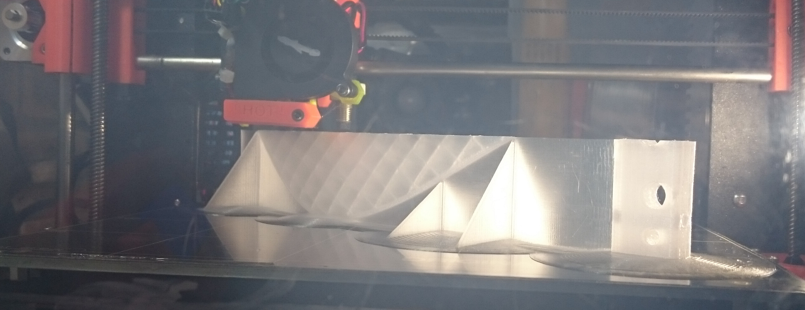
Fins as large as the 110% McCoy Gullwing fins (straight tip, original and extended tip versions) can be printed in one piece with the Original Prusa i3 MK2 when orientated the right way, and they will print stronger that way, too!
In a nutshell:
A) Use OpenScad to insert numerous very tiny cylinders. The size needs to be large enough or they disappear, but as small as possible so they do not really exist in the printed result. This forces the Slic3r to surround each cylinder with as many top and bottom layers as you set. With the right spacing, the entire area becomes solid.
B) Print the fin with the leading edge down. Later I’ll maybe try trailing edge down as well. This makes the filament layers run along the right direction for maximum strength. If printed standing on the tab, then the layers run at 90deg to the maximum forces experienced by the fin (when pulling into a barrel), and it snaps off, because inter-layer separation is the most likely failure mode of 3D printed objects. Like trying to snap a board of timber along or against the grain.
Here is the OpenScad code I used to make the 107 x 0.1mm radius cylinders:
!color(“red”)
rotate ([270,0,0])
translate ([-20,-0,-20])
union(){
// Front screw hole
translate([36.5,0,-5])
cylinder (r=2.1,h=45);
translate([0,0,0])
union(){
// Group of 17 short cylinders aft
translate([-127.5,0,0])
union(){
translate([37.5,0,0])
union(){
translate([-1.5,0,0]) cylinder (r=0.1,h=16);
translate([-3,0,0]) cylinder (r=0.1,h=16);
translate([-4.5,0,0]) cylinder (r=0.1,h=16);
translate([-6,0,0]) cylinder (r=0.1,h=16);
translate([-7.5,0,0]) cylinder (r=0.1,h=16);
translate([-9,0,0]) cylinder (r=0.1,h=16);
translate([-10.5,0,0]) cylinder (r=0.1,h=16);
}
translate([45,0,0])
union(){
translate([-1.5,0,0]) cylinder (r=0.1,h=16);
translate([-3,0,0]) cylinder (r=0.1,h=16);
translate([-4.5,0,0]) cylinder (r=0.1,h=16);
translate([-6,0,0]) cylinder (r=0.1,h=16);
translate([-7.5,0,0]) cylinder (r=0.1,h=16);
}
translate([52.5,0,0])
union(){
translate([-1.5,0,0]) cylinder (r=0.1,h=16);
translate([-3,0,0]) cylinder (r=0.1,h=16);
translate([-4.5,0,0]) cylinder (r=0.1,h=16);
translate([-6,0,0]) cylinder (r=0.1,h=16);
translate([-7.5,0,0]) cylinder (r=0.1,h=16);}
}
translate([-67.5,0,0])
union(){
translate([-1.5,0,0]) cylinder (r=0.1,h=45);
translate([-3,0,0]) cylinder (r=0.1,h=40);
translate([-4.5,0,0]) cylinder (r=0.1,h=35);
translate([-6,0,0]) cylinder (r=0.1,h=30);
translate([-7.5,0,0]) cylinder (r=0.1,h=25);}
translate([-60,0,0])
union(){
translate([-1.5,0,0]) cylinder (r=0.1,h=53);
translate([-3,0,0]) cylinder (r=0.1,h=52);
translate([-4.5,0,0]) cylinder (r=0.1,h=51);
translate([-6,0,0]) cylinder (r=0.1,h=50);
translate([-7.5,0,0]) cylinder (r=0.1,h=49);}
translate([-52.5,0,0])
union(){
translate([-1.5,0,0]) cylinder (r=0.1,h=58);
translate([-3,0,0]) cylinder (r=0.1,h=57);
translate([-4.5,0,0]) cylinder (r=0.1,h=56);
translate([-6,0,0]) cylinder (r=0.1,h=55);
translate([-7.5,0,0]) cylinder (r=0.1,h=54);}
translate([-45,0,0])
union(){
translate([-1.5,0,0]) cylinder (r=0.1,h=62);
translate([-3,0,0]) cylinder (r=0.1,h=61);
translate([-4.5,0,0]) cylinder (r=0.1,h=60);
translate([-6,0,0]) cylinder (r=0.1,h=60);
translate([-7.5,0,0]) cylinder (r=0.1,h=59);}
translate([-37.5,0,0])
union(){
translate([-1.5,0,0]) cylinder (r=0.1,h=69);
translate([-3,0,0]) cylinder (r=0.1,h=68);
translate([-4.5,0,0]) cylinder (r=0.1,h=66);
translate([-6,0,0]) cylinder (r=0.1,h=64);
translate([-7.5,0,0]) cylinder (r=0.1,h=62);}
translate([-30,0,0])
union(){
translate([-1.5,0,0]) cylinder (r=0.1,h=74);
translate([-3,0,0]) cylinder (r=0.1,h=73);
translate([-4.5,0,0]) cylinder (r=0.1,h=72);
translate([-6,0,0]) cylinder (r=0.1,h=71);
translate([-7.5,0,0]) cylinder (r=0.1,h=70);}
translate([-22.5,0,])
union(){
translate([-1.5,0,0]) cylinder (r=0.1,h=85);
translate([-3,0,0]) cylinder (r=0.1,h=82);
translate([-4.5,0,0]) cylinder (r=0.1,h=78);
translate([-6,0,0]) cylinder (r=0.1,h=76);
translate([-7.5,0,0]) cylinder (r=0.1,h=75);}
translate([-15,0,0])
union(){
translate([-1.5,0,0]) cylinder (r=0.1,h=101);
translate([-3,0,0]) cylinder (r=0.1,h=97);
translate([-4.5,0,0]) cylinder (r=0.1,h=93);
translate([-6,0,0]) cylinder (r=0.1,h=89);
translate([-7.5,0,0]) cylinder (r=0.1,h=85);}
translate([-7.5,0,0])
union(){
translate([-1.5,0,0]) cylinder (r=0.1,h=125);
translate([-3,0,0]) cylinder (r=0.1,h=120);
translate([-4.5,0,0]) cylinder (r=0.1,h=115);
translate([-6,0,0]) cylinder (r=0.1,h=110);
translate([-7.5,0,0]) cylinder (r=0.1,h=105);}
// Longest set just aft of notch
union(){
translate([-1.5,0,0]) cylinder (r=0.1,h=150);
translate([-3,0,0]) cylinder (r=0.1,h=145);
translate([-4.5,0,0]) cylinder (r=0.1,h=140);
translate([-6,0,0]) cylinder (r=0.1,h=135);
translate([-7.5,0,0]) cylinder (r=0.1,h=130);}
// elevated group of cylinders front
translate([7.5,0,50])
union(){
translate([-1.5,0,7]) cylinder (r=0.1,h=19);
translate([-3,0,4]) cylinder (r=0.1,h=30);
translate([-4.5,0,1]) cylinder (r=0.1,h=41);
translate([-6,0,0]) cylinder (r=0.1,h=62);
translate([-7.5,0,0]) cylinder (r=0.1,h=83);}
translate([7.5,0,0])
union(){
translate([-1.5,0,0]) cylinder (r=0.1,h=19);
translate([-3,0,0]) cylinder (r=0.1,h=20);
translate([-4.5,0,0]) cylinder (r=0.1,h=21);
translate([-6,0,0]) cylinder (r=0.1,h=22);
translate([-7.5,0,0]) cylinder (r=0.1,h=23);}
translate([15,0,0])
union(){
translate([-1.5,0,0]) cylinder (r=0.1,h=16);
translate([-3,0,0]) cylinder (r=0.1,h=16);
translate([-4.5,0,0]) cylinder (r=0.1,h=17);
translate([-6,0,0]) cylinder (r=0.1,h=17);
translate([-7.5,0,0]) cylinder (r=0.1,h=18);
}
translate([22.5,0,0])
union(){
translate([-1.5,0,0]) cylinder (r=0.1,h=16);
translate([-3,0,0]) cylinder (r=0.1,h=16);
translate([-4.5,0,0]) cylinder (r=0.1,h=16);
translate([-6,0,0]) cylinder (r=0.1,h=16);
translate([-7.5,0,0]) cylinder (r=0.1,h=16);
}
translate([30,0,0])
union(){
translate([-1.5,0,0]) cylinder (r=0.1,h=16);
translate([-3,0,0]) cylinder (r=0.1,h=16);
translate([-4.5,0,0]) cylinder (r=0.1,h=16);
translate([-6,0,0]) cylinder (r=0.1,h=16);
translate([-7.5,0,0]) cylinder (r=0.1,h=16);
}
translate([37.5,0,0])
union(){
translate([-1.5,0,0]) cylinder (r=0.1,h=16);
translate([-3,0,0]) cylinder (r=0.1,h=16);
translate([-4.5,0,0]) cylinder (r=0.1,h=16);
translate([-6,0,0]) cylinder (r=0.1,h=16);
translate([-7.5,0,0]) cylinder (r=0.1,h=16);
}
translate([45,0,0])
union(){
translate([-1.5,0,0]) cylinder (r=0.1,h=16);
translate([-3,0,0]) cylinder (r=0.1,h=16);
translate([-4.5,0,0]) cylinder (r=0.1,h=16);
translate([-6,0,0]) cylinder (r=0.1,h=16);
translate([-7.5,0,0]) cylinder (r=0.1,h=16);
}
translate([52.5,0,0])
union(){
translate([-1.5,0,0]) cylinder (r=0.1,h=16);
translate([-3,0,0]) cylinder (r=0.1,h=16);
translate([-4.5,0,0]) cylinder (r=0.1,h=16);
translate([-6,0,0]) cylinder (r=0.1,h=16);
translate([-7.5,0,0]) cylinder (r=0.1,h=16);}
}
}
}
//}

Aliens trying to help build fins in a better way?
Or just me loosing the plot.
Anyhow, I’m starting to understand what those crop circles are about…
That’s what they are for:
ROTFLMAO

Here is the latest cropcircle iteration.
I had to reduce the ‘Brim’ to 10mm so it can fit on the 250x210mm build plate of the printer. The fin uses the entire 200mm z-axis height of the printer as well.
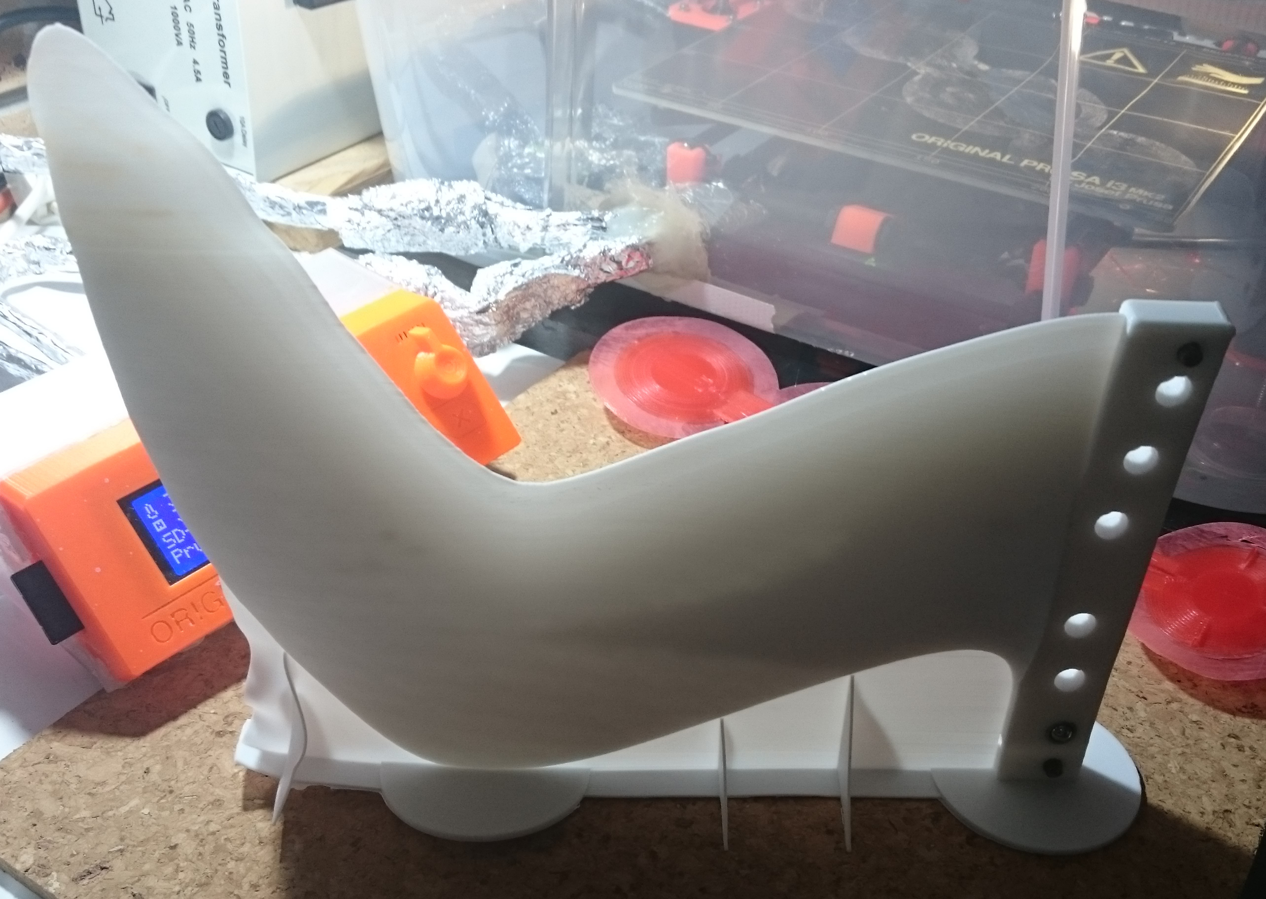
The round and oval plates are now conical, this reduces warping forces and material use, without weakening it, and makes it much easier to get the fin off the build plate when the print is finished.
The side stabilisers are now supported by the 2mm thick conical plates to reduce the risk of them pulling off the print bed.
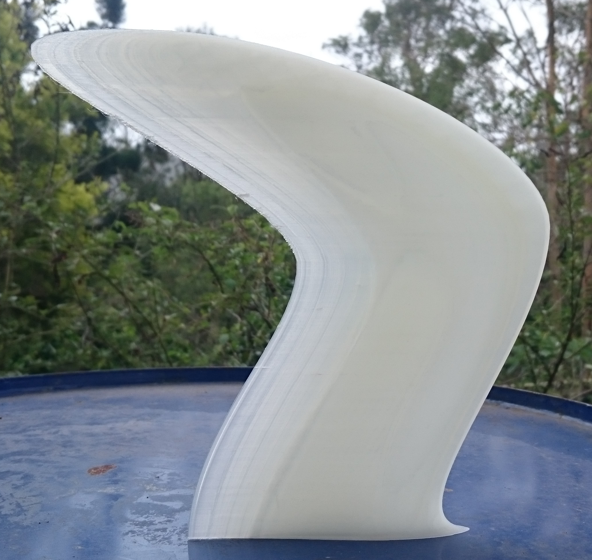
The last print attempt with Polymaker PC-Max went well and actually completed, but I ruined the fin by heating it too much when trying to anneal it in the kitchen oven.
Several attempts using polycarbonate filament have gone spectacularly wrong. I have found a way to prevent the polycarbonate from pulling off the build plate due to warping forces, but when the fin cannot warp by coming off the build plate, then it literally tears itself apart due to warping. The Polymaker PC-Max is a lot more forgiving.
The fin does not float, so I am printing the next one with thinner walls and less infill, which will also reduce warping forces. I’m trying out Polymaker PC-Plus transparent filament for the first time, looking good so far.
I have also tweaked the .gcode instructions for the printer so that hopefully the print speed will gradually reduce to a very slow speed at the end, when the layer print time gets too short for the filament to cool before the next layer is deposited on it. I hope it will gradually slow down to 1mm/s print speed while it is approaching the tip of the fin. That way, less supervision is required (if it works as intended).
The white fin shown took 30hrs to print (and 5 minutes to ruin in the kitchen oven)!


Another failed print;
The oval pad at the distal fin end lifted off the print bed due to warping forces. I did not see it happen, but it appears to me that it warped so much that the distal end of the fin was lifted up until it stopped the nozzle from moving. This causes ‘missed steps’ of the stepper motors, and henceforth the printer does no longer know the position of the nozzle. It prints the rest of the fin with a ‘layer shift’.
How much the material has to do with it is unknown, it’s the first time I used Polymaker PC-Plus.
I also changed the bed temperature, from 110C for the entire print, to 110C first layer, then 80C for the rest. I’m hoping this will reduce damage to the PEI sheet covering the bed. It is showing severe damage from the warping of the fins when they do not lift off the bed. The forces are so strong that they lift the PEI sheet off the bed. The worst damage was done by the fin that completed printing. from Polymaker PC-Max. I did not have an oval pad under the distal end at the time. The rectangular small pad concentrated lifting forces and produced a permanent bubble of lifted PEI sheet.
So it’s back to printing with Polymaker PC-Max, new supply has arrived, black and white are the only available colours. I’ll go back to trying other materials when I had success with this one. Although, working with the extremely tricky polycarbonate results in more obvious failures, faster, and therefore faster learning and improvement of the print technique.
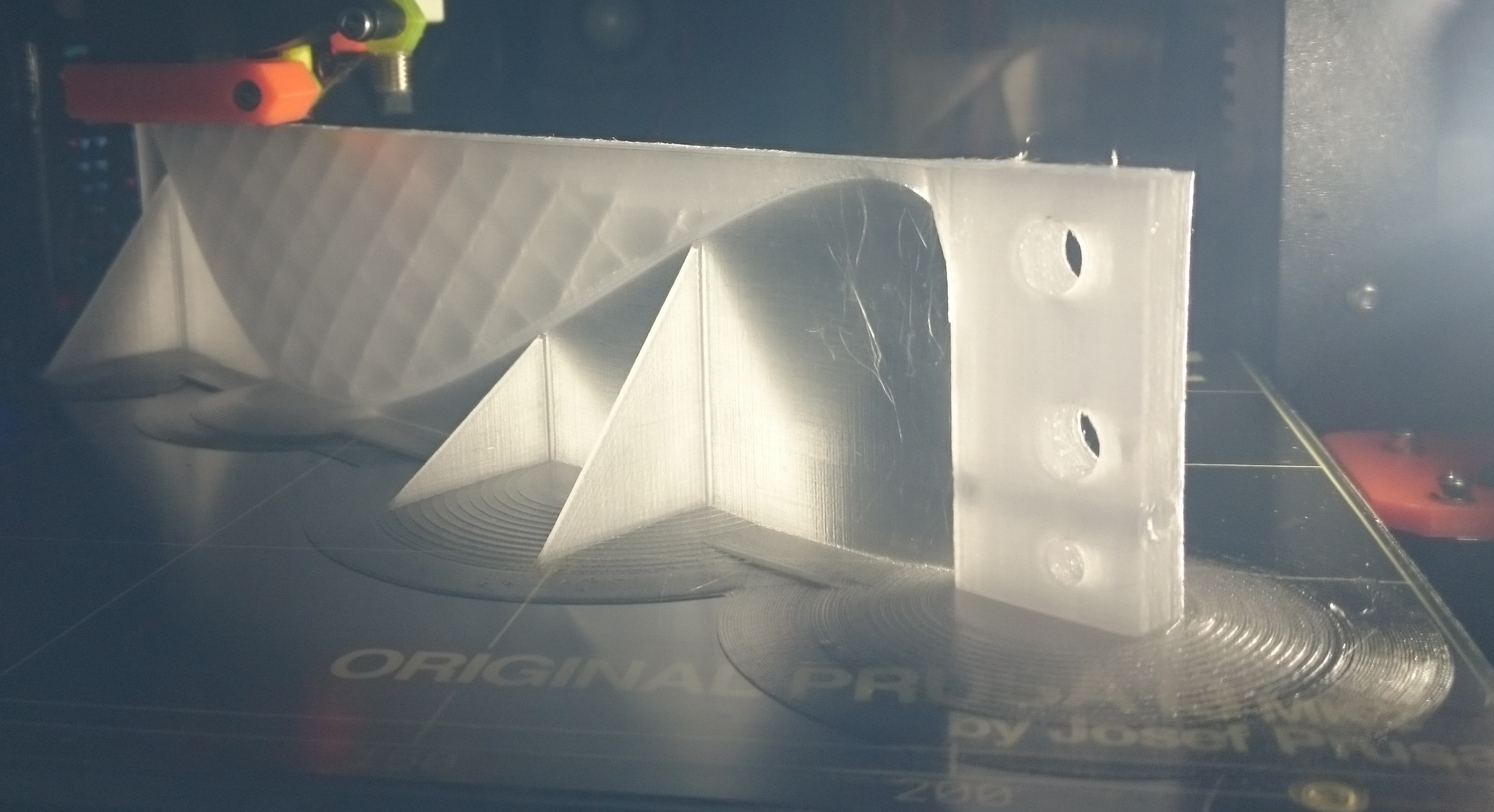
In the latest version I changed the thin support wall to a lattice, to minimise the warp component introduced by the wall.
And the number of perimeters has been reduced to 3, with cubic infill 10%.
Nozzle 270C, bed 110C first layer, 80C the rest.
Filament cooling fan disabled.
No ABS juice on bed, but thorough acetone clean before printing.
Enclosure closed for entire print (is the plan), about 34C with very low humidity in the enclosure.
And I have reduced the printing speed to 50% at the start of the print. I read somewhere that slower printing can reduce warping, not sure if that actually works. The speed reduction was not programmed into the Gcode file, but manually adjusted via “Tune” function of the LCD control of the printer.
It’s looking good so far, except for a crack through the fin tab where the hole for the screw is, and some mystery blobs that I did not observe being created and I do not understand them yet. See photo. I’ll get rid of the screw hole or make it a thin guide for drilling, because it introduces a weak point for layer separation.
I’m moving the bulk of my effort to document this to the Prusa forum.
That way, it’s more likely that I will get advice to tackle the ongoing difficulties.
I think the forum is open for read only without registration, let me know if not.
http://shop.prusa3d.com/forum/print-tips-slic3r-settings-kisslicer-model-repair--f12/printing-a-large-surfboard-fin-t2675.html
I’m happy to answer questions here (if there are any), so no need for you to sign up to another forum if you want to follow this.
Even if the print fucks up again, it looks damn pretty (if you ask me).
No aliens where harmed (or consulted) in the process, but I could certainly do with some help …
Looking good MrMik. I see you got some feedback on the other forum and your current solution looks interesting.
Thanks, jrandy!
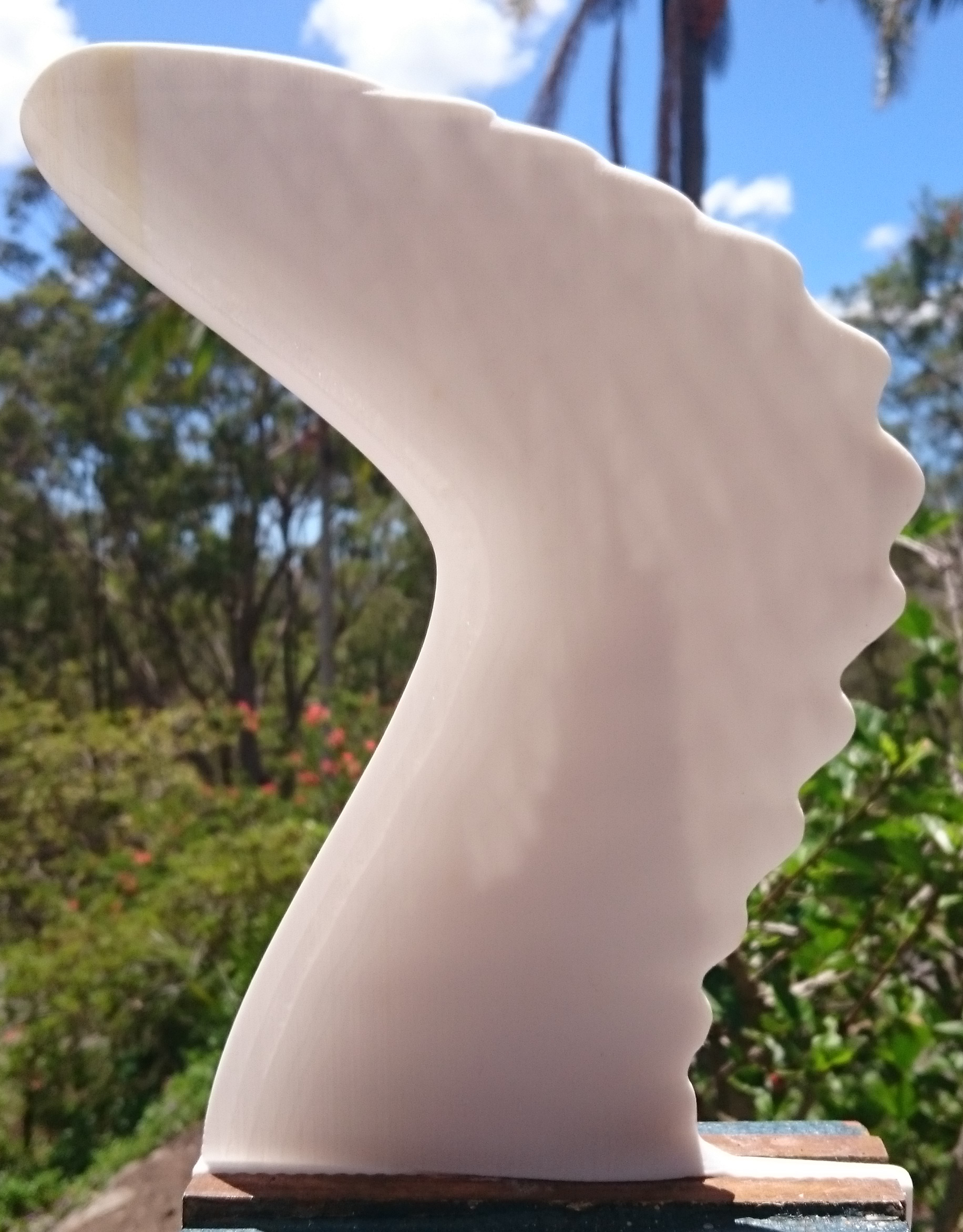
I managed to print a fin and actually surf the thing.
Wanderfalke-2-1-Whale_UTFB_1-5-1-3-3-3-7-8_PC-Plus_0p25mm.gcode
The good news is, it did not snap off or fall out of the fin box, but it still has a number of issues that I’m trying to iron out.
The material is a bit soft, it flexes more than other fins, I don’t know if that is good or bad or very bad. It felt very loose for pivoting moves, the waves were fat and fairly weak, 1.5m to 2m faces, barely breaking and crowded.
No chance for any steep barrelling sections to test if the fin will snap off under strong load, so it’s too early to tell if it’s durable enough.
One good thing about the fin base warping a little is that it holds it in the box very nicely. No need for ball spring plungers, less weight, less cost.
This fin only just floats in fresh water with 6 BSPs in it.
Hi MrMik, just a few thoughts…
Have you considered that the warping could be minimised by stalling the print so it cools.
Or printing side vanes that stabilise the print as it’s created.
And would It b possible and faster to print fin ‘shells’ that can have a carbon / lantor soric vacbagged interior ?
Maybe the future is a 3D shell with a CNC core and all vacbagged together ?