Fantastic MrMik!
S R F D C O, the trend in rapid prototyping is 3d printing molds for small runs-less time and cost making the tool and more material choices for the parts.
I’m sure once I really understand warping, it will be obvious and easy and straight-forward.
For now, it is still quite confusing, but I’m beginning to understand it.
Printing slower helps with many 3D printing issues. That’s because 3D printing is so slow that there is always a push to make it faster, until problems arise.
So, in that sense, printing slower can sometimes help with warping and with other problems. But it would not help because it gives time to cool down.
One basic warping mechanism is this: One layer is printed, then it cools and it contracts, shortens, a little bit. If it has shortened to the maximum, i.e. it has cooled down to room temperature before the next layer is hot-glued to it, then the the next layer will contract after binding with the first layer, and bend it in the process. Each layer adds a bit to this.
the cure for this particular warping scenario is to lay down the next layer before the previous one has contracted. Best achieved by keeping it all very warm, or hot, basically as hot as it can be before it starts to deform when it hits the " Glass Transition Temperature" of the particular material being extruded.
I f you can keep the extruded material close to it’s glass transition temperature while you deposit further layers on top of the still hott-ish ones, then annealing occurs while your printed object slowly grows, and you get no warping.
So for now, I’m concentrating on developing a “re-useable heated enclosure” instead of the 'Sacrificial Heated Enclosure" that I used with good success for the fin that I surfed, and several other prints after it. I printed an enclosure around the printing object, keeping in the heat from the heated bed. I also optimised the heating by installing a cork tile under the heated bed, and a silicone sock around the hot end of the extruder. Now I can print with 120C bed temperature and up to 295C nozzle temperature, and keep the heat concentrated around the printing part.
The downside of the sacrificial heated enclosure (SHE) is that about 40% of the filament used for the print is being wasted. That means electricity to melt it, time to print it, and the plastic itself, and landfill. That might be a bit better than sanding back a laminated slab of material to make a fin, but it’s not good enough.
So now I’m trying to print parts that can be assembled gradually around the printing part, manually, and reused many times for various prints.
The general idea is to print a sacrificial tongue with each fin (or other object), rather than a complete SHE.
Below is the SCAD code, you’ll understand what I mean it you have a look at the object in SCAD. It can be ‘split’ in Slic3r into two parts that (hopefully) fit together without noticeable air gaps to let in cold drafts. Every time the print has progressed by another 10mm or so, add the next layer of the re-useable heated enclosure (RHE).
It’s printing at the moment, and might be badly flawed in some unexpected (by me) way, but looking good so far.
Wanderfalke-2-1-W_UTFB_1-6-4-6-4-3Enclosureonly.scad code:
$fn=80;
difference(){
union(){
rotate([0,0,-39.5])
union(){
// Reusable enclosure:
union(){
// Tounge ellipse 2mm wide:
// differencing groove from tounge:
difference(){
// Union of tounge ellipse:
union(){
color(“red”){
translate([0,0,5])
difference(){
rotate([0,0,0])
scale([159,34,0.1])
linear_extrude([0,0,0.5])
circle(1);
rotate([0,0,0])
scale([157,32,0.1])
linear_extrude([0,0,0.5])
circle(1);}}}
// Groove ellipse differenced from tounge ellipse:
translate([0,0,-4])
union(){
difference(){
rotate([0,0,0])
scale([159.5,34.5,0.1])
linear_extrude([0,0,0.5])
circle(1);
rotate([0,0,0])
scale([156.5,31.5,0.1])
linear_extrude([0,0,0.5])
circle(1);} }
}
// Inner wall segment
difference(){
union(){
difference(){
rotate([0,0,0])
scale([159,34,0.1])
linear_extrude([0,0,1])
circle(1);
rotate([0,0,0])
scale([153,29,0.1])
linear_extrude([0,0,1])
circle(1);}}
// Groove ellipse differenced from inner wall:
translate([0,0,-4])
union(){
difference(){
rotate([0,0,0])
scale([159.5,34.5,0.1])
linear_extrude([0,0,0.5])
circle(1);
rotate([0,0,0])
scale([156.5,31.5,0.1])
linear_extrude([0,0,0.5])
circle(1);} }
}
// Outer half of wall segment:
difference(){
union(){
difference(){
rotate([0,0,0])
scale([163,38,0.1])
linear_extrude([0,0,1])
circle(1);
rotate([0,0,0])
scale([159,34,0.1])
linear_extrude([0,0,1])
circle(1);}}
// Groove ellipse differenced from outer wall:
translate([0,0,-4])
union(){
difference(){
rotate([0,0,0])
scale([159.5,34.5,0.1])
linear_extrude([0,0,0.5])
circle(1);
rotate([0,0,0])
scale([156.5,31.5,0.1])
linear_extrude([0,0,0.5])
circle(1);} }
}
}
}
}
color(“blue”){
rotate([0,0,-39.5])
translate([-10,24,0])
linear_extrude(0,0,15)
polygon([[0,0],[10,0],[10,10],[20,10],[20,20],[19.5,20],[19.5,10.5],[9.5,10.5],[9.5,0.5],[0,0.5]]);
rotate([0,0,-39.5])
translate([10,-24,0])
rotate([0,0,180])
linear_extrude(0,0,15)
polygon([[0,0],[10,0],[10,10],[20,10],[20,20],[19.5,20],[19.5,10.5],[9.5,10.5],[9.5,0.5],[0,0.5]]);
}
}

I’ve had some fins and fin boxes printed and the current affordable plastics aren’t strong enough to survive the forces involved in surfing, these items were printed by professional printers who surf but is there a certain plastic that’s most suitable or maybe printing is better suited to thicker fins and solid items ?
Polycarbonate is the most suitable material at this stage.
Unfortunately, it is fickle, needs a heated chamber and higher printing temperatures than most printers can achieve.
Without heated chamber, it warps badly, particularly for large items like fins.
Polymaker PC-Max is a polycarbonate based material that is easier to print than true PC. I currently print it at 270C nozzle temp and 120C bed temp with some success. But, it is more flexible than PC.
Once I have finished the re-useable enclosure, I’ll print a fin with holes for insertion of high tensile strength steel bolts, and fill the rest with resin.

MrMik, what would you say is the quality of the surface finish of printing ? Is it something that will ever be comparable to a gloss coat ?
The surface finish currently achievable with home-3d printers is very rough compared to a gloss coat.
Polymaker PC-Max can be sanded well, so surface finish can be improved.
A better surface finish can be achieved by printing with smaller layer height, but that reduces strength, because the connections between the layers are the weakest point.
Thicker layers = less layer boundaries = better strength = rougher surface.
If this is hydro-dynamically important, or even better than glossy, is another question.
I ask about the finish because the repeatable accuracy, autonomous production and computer control are all a plus but without a great surface finish its not perfect. Do you know if any of the printing materials are compatible with any resins ? Will any resin chemically bond with the printing plastics ?
The big problem is the strength. If your fin snaps off when you are about to pull into a barrel in a crowded location, or at a reef break, that’s not very nice.
Surface finish is something I’ll worry about much later, when the big issues are sorted out.
I think I’ll probably end up painting the fins anyway, that will seal any leaks and provide UV protection, and a customisable colour and potential glossy surface finish.
I have not systematically tested resin adhesion to 3D printing materials, but with rough-ish surface, and some (unwanted) porosity, I bet epoxy resin will hang on to it well enough.
The reusable enclosure segments stack is growing, while I make incremental adjustments and tweak the printing settings:

This link just came up on the 3D print Prusa forum, it’s about surface finish on 3D printed fins.
Almost ready to start printing with a different approach: Trailing edge down.
Most likely it will again fail in some way or another, resulting in another lesson learned…
I concocted some H-beams as supports, added hollow spaces to screw in steel rods, and added some tailored infill instead of letting the slicing software fill the entire space.
The result will hopefully be an accurate outer shell, more than strong enough to hold it’s shape when filled with epoxy resin, and very strong when high tensile strength steel rods are added into the mix.

i don’t think any of the plastics alone will have enough stiffness for a good surfboard fin…maybe Ultem but it requires an expensive machine. There are some pretty cool material/methods that is incorporating fiber into the plastic and those would probably make a nice surfboard fin. Vulcan surfboards has been doing a carbon print fin and glassing them on - so i guess resin compatible (and also maybe not strong enough for boxes thats why they would be glassed on?) check out the markforged 3-D printers. they use nylon as a base and have threads that contain chopped carbon or chopped fiberglass. they also have a method to incorporate continuous carbon tow with the nylon matrix. pretty cool stuff and not expensive compared to an industrial 3-D printer (but more expensive compared to a low end home use machine).
great effort, great thread!
abs would probably make a decent resin compatible box
Plastic 3D printed fins are quite flexible indeed.
I don’t own a 3D printer, I have them printed by a professional shop. (sintered instead of fused deposit, so no hassle with all supports and stuff)
For thruster or small single fins, the flexibility is not too bad.
Just make them a little thicker if you want them stiffer.
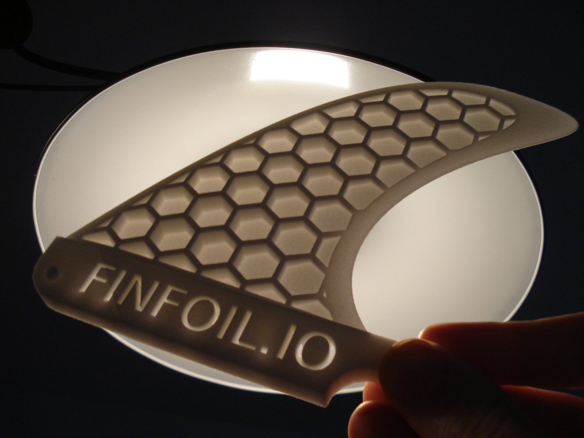
Hans, that’s a fine looking fin.
What program did you use to get the hex pattern in the center? I haven’t done much 3d printing, and am curious as to what I’d need to give to a professional shop to have them print out a fin with a hex pattern in the center. Am I correct in assuming there is a thin skin of plastic on both sides over the hex?
The fin pictured is a demo model to show the internal structure. Here is it in 3D: http://finfoil.io/s/r/j63w
The fins have a skin thickness of +/-2mm.
The internal structure is created using some custom OpenSCAD scripts.
I can feed them any finfoil created 3D file and the script will automatically create the internal structure.
Below you can find an image of the closed surface.
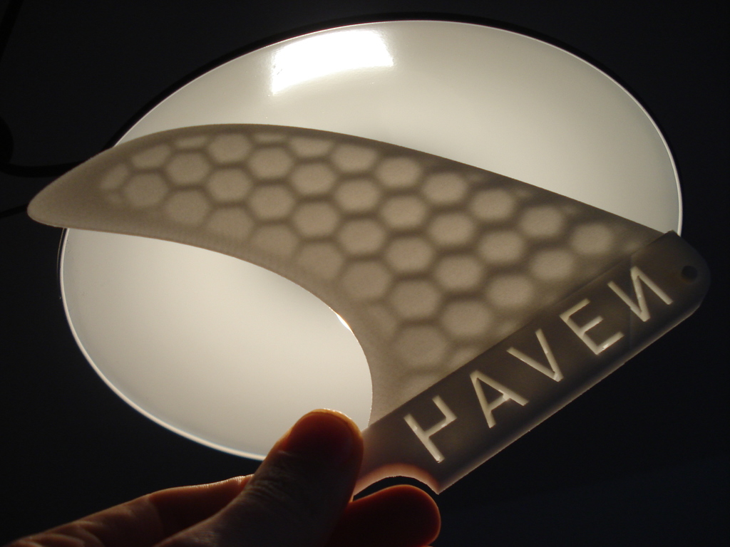
It comes straight from the printer like this, no post processing required.
Thanks for the info Hans. I’ve often thought about making fins with a honeycomb interior, and this looks like a very interesting method to explore.