Suffoils wrote:“That amazing Mr Mik ! So much progress and innovation.
Can I buy one please ?”
Thank you very much!
You’ll get a free one if i manage to get it right.
I’m not sure I want to sell fins, and they are not quite ready.
Suffoils wrote:“That amazing Mr Mik ! So much progress and innovation.
Can I buy one please ?”
Thank you very much!
You’ll get a free one if i manage to get it right.
I’m not sure I want to sell fins, and they are not quite ready.
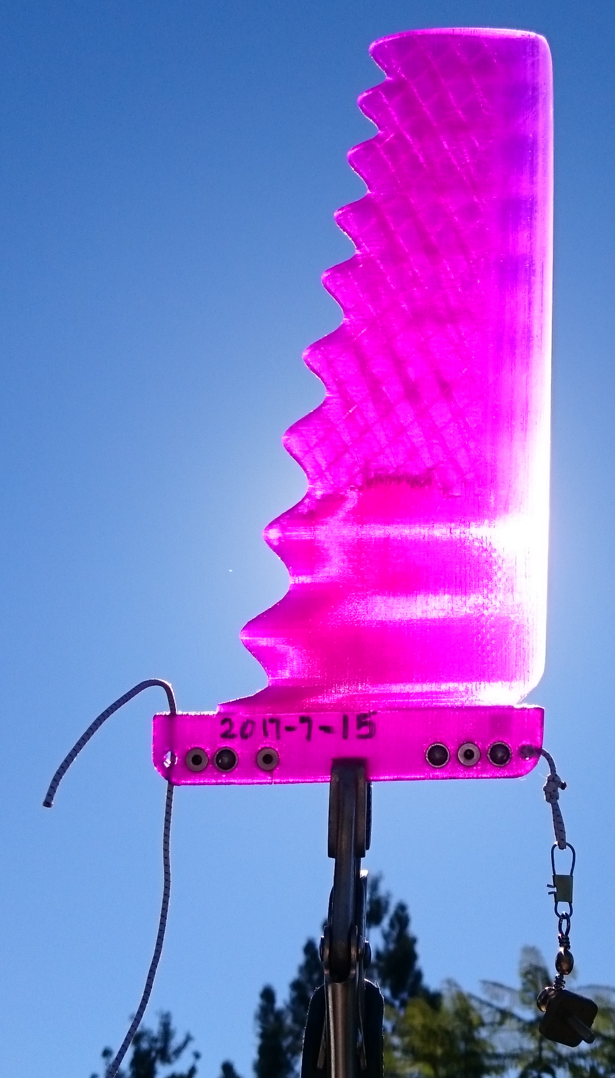
WF2BLEF2163HRx30x1.3mm_UTFB3017infillb_X3DtpPLA-EM1.129_0p15mm_20170418.gcode has stood up to a surf session at Burleigh without much damage.
This is the fin printed with infill, then carbon rods inserted, no resin fill. It has printing faults and I used it without ball spring plungers (BSPs) because it seemed to fit firmly in the box without them.
The waves were up to 2m faces, sucky, mostly closing out. Lots of getting hammered in the impact zone after each short ride.
The fin tended to move out of the box by 1-2mm on several occasions but never came all the way out. I guess that means that the BSPs are actually doing something, they prevent the first bit of movement of the fin out of the box. During the previous surf with a fin with BSPs there was no movement of the fin.
The fin took in water. It ended up 15g heavier after the surf compared to before the surf. I don’t know yet how much of a problem that is going to be. The main water reservoir seems to be the hollow carbon tubes. I shall seal their ends properly with the next fin.
.
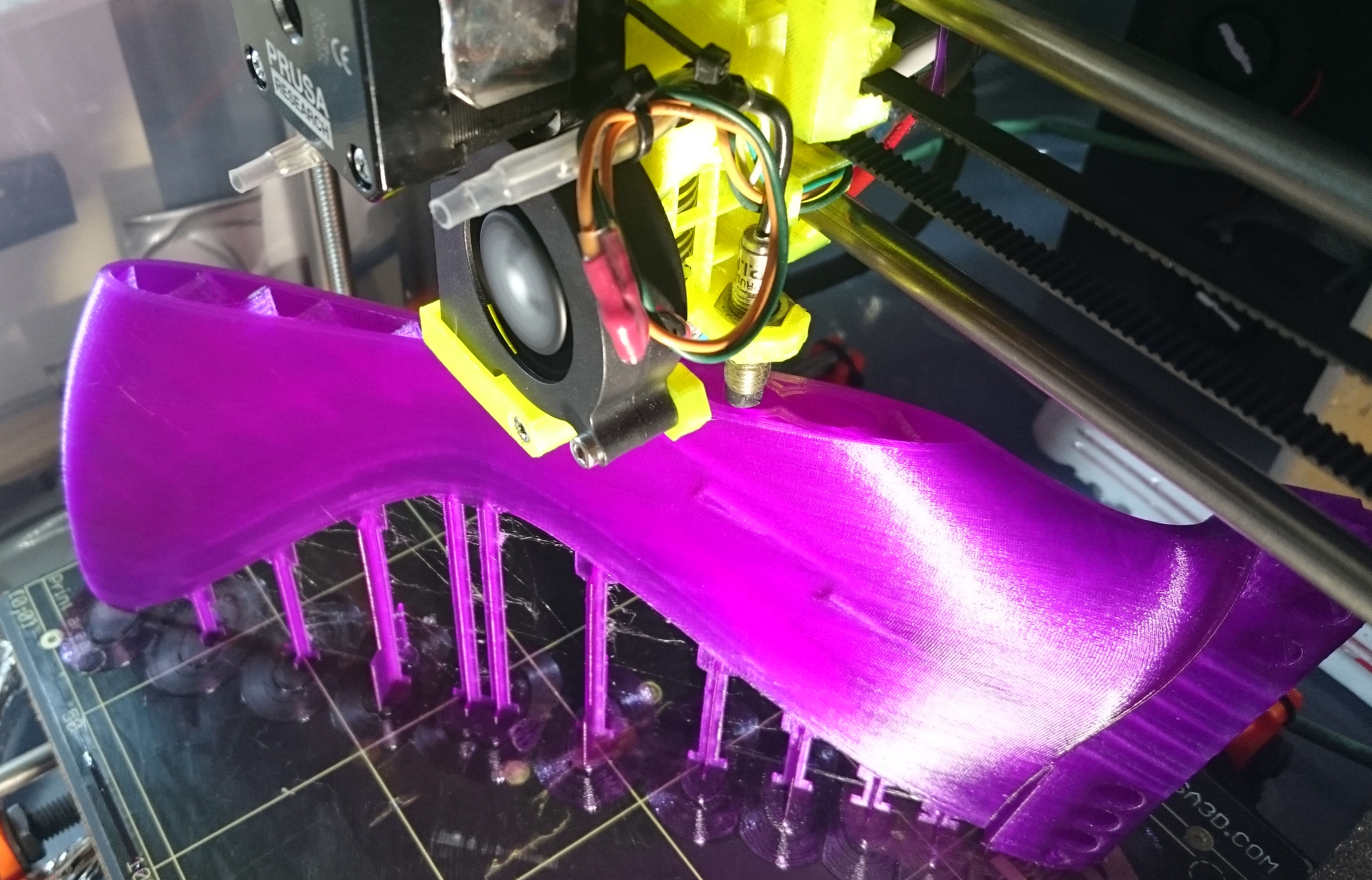
The next print of the same file went better, but there are still some minimal layer shifts. I think I went too far with the recent slimming down of the support posts and the fin wobbles a bit during printing, causing the problems. Total print time, uninterrupted this time, was 29h27min.
.
With the next print (running at the moment) I try a higher print temperature (230C first layer, 225C the rest instead of 230/210C). Maybe that will cause less water leaks.
I have also strengthened some of the support posts selectively and added in a hole for the swivel security attachment string. That way I don’t need to drill any holes. And infill is reduced from 20% to 5%.
Seriously… this is the kind of stuff that has always made Swaylocks so great. I have a bit of a fin project going on myself and this thread has been a real education. I am happy to see some other people on here. I’m sure they know who they are!
Many thanks to MrMik, JRandy, stoneburner, hans, the artist formerly known as Surfoils, and everybody else who has contributed.
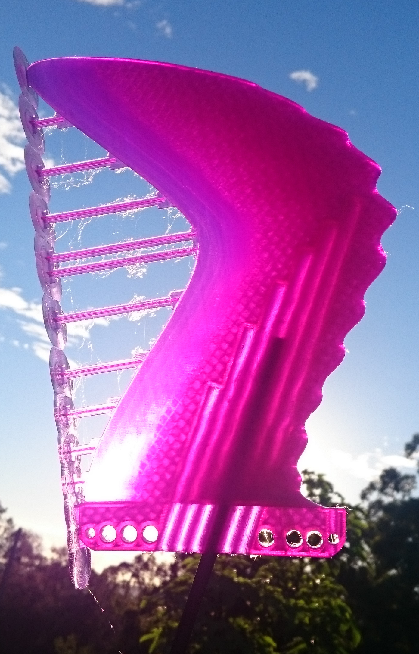
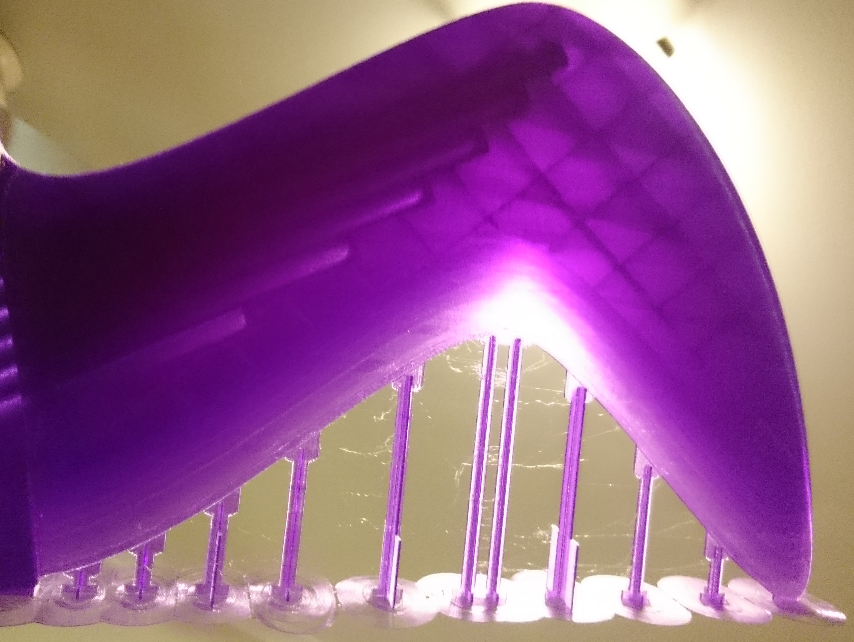
The smooth leading edge version printed very well.
The reinforced supports seem to work.
If the higher printing temperature has an effect, I’m not so certain. The temperature displayed fluctuates wildly, I really need to fix the failing cables properly. Upgrade kit from Prusa i3MK2 to MK2s is in the mail, it looks promising for fixing this cable breakage problem.
The reduced infill gives a different look when transilluminating the fin, much bigger empty spaces. It does not feel weak, I have not inserted the carbon rods yet.
Weight including supports is 187g (the 20% infill BLEF fin weighed 232g).
Of course if it leaks, then it has so much more space to accumulate salt water. And exactly what that means, considering the claimed ‘biodegradable’ nature of the PLA plastic, remains to be seen.
I think I will probably end up using the ‘print a hollow shell and fill with q-cel resin’ approach in the end, just to keep the salt water out of the fins.
And painting the fins to seal and protect them is an option as well.
MrMik, That’s genius right there !!
johnMellor, It’s been a long winding journey into the machinations of fin design, 3-D printing and the physics of engineering. And why not ! It’s been brilliant.
Below is the OpenScad code (996lines of it!).
It contains some notes to make it easier to use, for I know that in a year I will no longer understand how much of it works. And then it could be tricky to try to adapt it to a new fin project.
However, with the notes included in the code, and a very basic understanding of how OpenScad works, you can adapt it quite easily to work for different fins.
.
.
.
WF2SLEF2226HRx30x0p8mm_UTFB3018infill.scad
$fn=75;
rotate([0,0,78.75]) // Rotate for alternative diagonal position on print bed
rotate([0,0,-39.5]) // Rotate union of it all so it fits on print table diagonally in Slic3r
difference(){// to make hole for swivel string
union(){ // union of it all
union(){ // union of X-beams and base plates
translate([-153,0,0])
union(){ // 13th topmost x-beam support
translate([0,0,1])
cube([10,0.8,2],center=true);
translate([0,0,0.1])
cube([0.8,10,0.2],center=true);
union(){//pad for 13th x-beam
linear_extrude(height=0.4){
scale([0.9,1.5,0])
circle(7.5);}
linear_extrude(height=0.2){
scale([0.9,1.5,0])
circle(10);}}}
//
translate([-126,0,0])
union(){ // 12th x-beam support
difference(){// differencing hollowed x-beam from original x-beam
union(){//original x-beam union
translate([0,0,12.5])// reduce z to move longitudinal part down
cube([10,0.8,25],center=true);// make 7mm longer than transverse cube z-value;reduce z to make longitudinal part shorter; must be double of above translate z value
translate([0,0,9])// reduce z to move transverse part down
cube([0.8,10,18],center=true); // reduce z to make transverse part shorter; must be double of above translate z value
}
//End original x-beam union
// translate([0,-40,0]) //to see it better when editing
color(“red”){
union(){//hollowed-out x-beam
difference(){//making ‘hollow’ x-beam
union(){ // old big x-beam
translate([0,0,8])// set to about 60% of longitudinal translate z-value; reduce z to move longitudinal thinner part down
cube([10,0.8,11],center=true);// set to about 60% of longitudinal cube z-value; reduce z to make longitudinal thin part narrower
translate([0,0,12])//set to transverse part z-translate value +3mm; reduce z to move transverse thinner part down
cube([0.8,10,18],center=true); //set to same height as transverse cube z-value; reduce z to make transverse thin part narrower
}
//end union old big x-beam
union(){ // new slim x-beam
translate([0,0,34])
cube([5,0.8,68],center=true);
translate([0,0,31.5])
cube([0.8,5,63],center=true);
}
//end union new slim x-beam
}
// End making ‘hollow’ x-beam
}
}//End color red
//end union hollowed out x-beam
}
//end differencing hollowed x-beam from original x-beam
union(){// Double base plate
linear_extrude(height=0.4){
scale([0.9,1.5,0])
circle(7.5);}
linear_extrude(height=0.2){
scale([0.9,1.5,0])
circle(10);}}
}
// End union 12th x-beam support
translate([-98,0,0])
union(){ // 11th x-beam support
difference(){// differencing hollowed x-beam from original x-beam
union(){//original x-beam union
translate([0,0,25])// reduce z to move longitudinal part down
cube([10,0.8,50],center=true);// make 7mm longer than transverse cube z-value;reduce z to make longitudinal part shorter; must be double of above translate z value
translate([0,0,21.5])// reduce z to move transverse part down
cube([0.8,10,43],center=true); // reduce z to make transverse part shorter; must be double of above translate z value
}
//End original x-beam union
// translate([0,-40,0]) //to see it better when editing
color(“red”){
union(){//hollowed-out x-beam
difference(){//making ‘hollow’ x-beam
union(){ // old big x-beam
translate([0,0,21])//reduce z to move longitudinal thinner part down
cube([10,0.8,36],center=true);//reduce z to make longitudinal thin part narrower
translate([0,0,24.5])//set to transverse part z-translate value +3mm; reduce z to move transverse thinner part down
cube([0.8,10,43],center=true); //set to same height as transverse cube z-value; reduce z to make transverse thin part narrower
}
//end union old big x-beam
union(){ // new slim x-beam
translate([0,0,34])
cube([5,0.8,68],center=true);
translate([0,0,31.5])
cube([0.8,5,63],center=true);
}
//end union new slim x-beam
}
// End making ‘hollow’ x-beam
}
}//End color red
//end union hollowed out x-beam
}
//end differencing hollowed x-beam from original x-beam
union(){// Double base plate
linear_extrude(height=0.4){
scale([0.9,1.5,0])
circle(7.5);}
linear_extrude(height=0.2){
scale([0.9,1.5,0])
circle(10);}}
}
// End union 11th x-beam support
//
translate([-72,0,0])
union(){ // 10th x-beam support
 translate([0,0,10])// attempt at extra stabilising
 cube([0.8,20,20], center=true);// attempt at extra stabilising
difference(){// differencing hollowed x-beam from original x-beam
union(){//original x-beam union
translate([0,0,36])// reduce z to move longitudinal part down
cube([10,0.8,72],center=true);// make 7mm longer than transverse cube z-value;reduce z to make longitudinal part shorter; must be double of above translate z value
translate([0,0,33])// reduce z to move transverse part down
cube([0.8,10,66],center=true); // reduce z to make transverse part shorter; must be double of above translate z value
}
//End original x-beam union
// translate([0,-40,0]) //to see it better when editing
color(“red”){
union(){//hollowed-out x-beam
difference(){//making ‘hollow’ x-beam
union(){ // old big x-beam
translate([0,0,32])// set to about 60% of longitudinal translate z-value; reduce z to move longitudinal thinner part down
cube([10,0.8,59],center=true);// set to about 60% of longitudinal cube z-value; reduce z to make longitudinal thin part narrower
translate([0,0,36])//set to transverse part z-translate value +3mm; reduce z to move transverse thinner part down
cube([0.8,10,66],center=true); //set to same height as transverse cube z-value; reduce z to make transverse thin part narrower
}
//end union old big x-beam
union(){ // new slim x-beam
translate([0,0,36]) // set same value as original x-beam
cube([5,0.8,72],center=true);// set same value as original x-beam
translate([0,0,36])// set same value as translate z transverse value
cube([0.8,10,66],center=true); // change ‘Y’ value to make transverse part thicker or thinner;
}
//end union new slim x-beam
}
// End making ‘hollow’ x-beam
}
}//End color red
//end union hollowed out x-beam
}
//end differencing hollowed x-beam from original x-beam
union(){// Double base plate
linear_extrude(height=0.4){
scale([0.9,1.5,0])
circle(7.5);}
linear_extrude(height=0.2){
scale([0.9,1.5,0])
circle(10);}}
}
// End union 10th x-beam support
//
translate([-50,0,0])
union(){ // 9th x-beam support
difference(){// differencing hollowed x-beam from original x-beam
union(){//original x-beam union
translate([0,0,43])// reduce z to move longitudinal part down
cube([10,0.8,86],center=true);// make 7mm longer than transverse cube z-value;reduce z to make longitudinal part shorter; must be double of above translate z value
translate([0,0,39.7])// reduce z to move transverse part down
cube([0.8,10,79.4],center=true); // reduce z to make transverse part shorter; must be double of above translate z value
}
//End original x-beam union
// translate([0,-40,0]) //to see it better when editing
color(“red”){
union(){//hollowed-out x-beam
difference(){//making ‘hollow’ x-beam
union(){ // old big x-beam
translate([0,0,40])// set to about 80% of longitudinal translate z-value; reduce z to move longitudinal thinner part down
cube([10,0.8,74],center=true);// set to about 80% of longitudinal cube z-value; reduce z to make longitudinal thin part narrower
translate([0,0,42.7])//set to transverse part z-translate value +3mm; reduce z to move transverse thinner part down
cube([0.8,10,79.4],center=true); //set to same height as transverse cube z-value; reduce z to make transverse thin part narrower
}
//end union old big x-beam
union(){ // new slim x-beam
translate([0,0,43]) // set same value as original x-beam
cube([5,0.8,86],center=true);// set same value as original x-beam
translate([0,0,39.7])// set same value as translate z transverse value
cube([0.8,5,79.4],center=true); // set same value as cube z transverse value
}
//end union new slim x-beam
}
// End making ‘hollow’ x-beam
}
}//End color red
//end union hollowed out x-beam
}
//end differencing hollowed x-beam from original x-beam
union(){// Double base plate
linear_extrude(height=0.4){
scale([0.9,1.5,0])
circle(7.5);}
linear_extrude(height=0.2){
scale([0.9,1.5,0])
circle(10);}}
}
// End union 9th x-beam support
//
translate([-42,0,0])
union(){ // 8th x-beam support
difference(){// differencing hollowed x-beam from original x-beam
union(){//original x-beam union
translate([0,0,43])// reduce z to move longitudinal part down
cube([10,0.8,86],center=true);// make 7mm longer than transverse cube z-value;reduce z to make longitudinal part shorter; must be double of above translate z value
translate([0,0,39.7])// reduce z to move transverse part down
cube([0.8,10,79.4],center=true); // reduce z to make transverse part shorter; must be double of above translate z value
}
//End original x-beam union
// translate([0,-40,0]) //to see it better when editing
color(“red”){
union(){//hollowed-out x-beam
difference(){//making ‘hollow’ x-beam
union(){ // old big x-beam
translate([0,0,40])// set to about 80% of longitudinal translate z-value; reduce z to move longitudinal thinner part down
cube([10,0.8,74],center=true);// set to about 80% of longitudinal cube z-value; reduce z to make longitudinal thin part narrower
translate([0,0,42.7])//set to transverse part z-translate value +3mm; reduce z to move transverse thinner part down
cube([0.8,10,79.4],center=true); //set to same height as transverse cube z-value; reduce z to make transverse thin part narrower
}
//end union old big x-beam
union(){ // new slim x-beam
translate([0,0,43]) // set same value as original x-beam
cube([5,0.8,86],center=true);// set same value as original x-beam
translate([0,0,39.7])// set same value as translate z transverse value
cube([0.8,5,79.4],center=true); // set same value as cube z transverse value
}
//end union new slim x-beam
}
// End making ‘hollow’ x-beam
}
}//End color red
//end union hollowed out x-beam
}
//end differencing hollowed x-beam from original x-beam
union(){// Double base plate
linear_extrude(height=0.4){
scale([0.9,1.5,0])
circle(7.5);}
linear_extrude(height=0.2){
scale([0.9,1.5,0])
circle(10);}}
}
// End union 8th x-beam support
//
translate([-17,0,0])
union(){ // 7th x-beam support
translate([0,0,10])// attempt at extra stabilising
 cube([0.8,20,20], center=true);// attempt at extra stabilising
difference(){// differencing hollowed x-beam from original x-beam
union(){//original x-beam union
translate([0,0,36])// reduce z to move longitudinal part down
cube([10,0.8,72],center=true);// make 7mm longer than transverse cube z-value;reduce z to make longitudinal part shorter; must be double of above translate z value
translate([0,0,33])// reduce z to move transverse part down
cube([0.8,10,66],center=true); // reduce z to make transverse part shorter; must be double of above translate z value
}
//End original x-beam union
// translate([0,-40,0]) //to see it better when editing
color(“red”){
union(){//hollowed-out x-beam
difference(){//making ‘hollow’ x-beam
union(){ // old big x-beam
translate([0,0,32])// set to about 60% of longitudinal translate z-value; reduce z to move longitudinal thinner part down
cube([10,0.8,59],center=true);// set to about 60% of longitudinal cube z-value; reduce z to make longitudinal thin part narrower
translate([0,0,36])//set to transverse part z-translate value +3mm; reduce z to move transverse thinner part down
cube([0.8,10,66],center=true); //set to same height as transverse cube z-value; reduce z to make transverse thin part narrower
}
//end union old big x-beam
union(){ // new slim x-beam
translate([0,0,36]) // set same value as original x-beam
cube([5,0.8,72],center=true);// set same value as original x-beam
translate([0,0,36])// set same value as translate z transverse value
cube([0.8,10,66],center=true); // // change ‘Y’ value to make transverse part thicker or thinner; set same value as cube z transverse value
}
//end union new slim x-beam
}
// End making ‘hollow’ x-beam
}
}//End color red
//end union hollowed out x-beam
}
//end differencing hollowed x-beam from original x-beam
union(){// Double base plate
linear_extrude(height=0.4){
scale([0.9,1.5,0])
circle(7.5);}
linear_extrude(height=0.2){
scale([0.9,1.5,0])
circle(10);}}
}
// End union 7th x-beam support
//
translate([12,0,0])
union(){ // 6th x-beam support
difference(){// differencing hollowed x-beam from original x-beam
union(){//original x-beam union
translate([0,0,25])// reduce z to move longitudinal part down
cube([10,0.8,50],center=true);// make 7mm longer than transverse cube z-value;reduce z to make longitudinal part shorter; must be double of above translate z value
translate([0,0,21.5])// reduce z to move transverse part down
cube([0.8,10,43],center=true); // reduce z to make transverse part shorter; must be double of above translate z value
}
//End original x-beam union
// translate([0,-40,0]) //to see it better when editing
color(“red”){
union(){//hollowed-out x-beam
difference(){//making ‘hollow’ x-beam
union(){ // old big x-beam
translate([0,0,21])//reduce z to move longitudinal thinner part down
cube([10,0.8,36],center=true);//reduce z to make longitudinal thin part narrower
translate([0,0,24.5])//set to transverse part z-translate value +3mm; reduce z to move transverse thinner part down
cube([0.8,10,43],center=true); //set to same height as transverse cube z-value; reduce z to make transverse thin part narrower
}
//end union old big x-beam
union(){ // new slim x-beam
translate([0,0,34])
cube([5,0.8,68],center=true);
translate([0,0,31.5])
cube([0.8,5,63],center=true);
}
//end union new slim x-beam
}
// End making ‘hollow’ x-beam
}
}//End color red
//end union hollowed out x-beam
}
//end differencing hollowed x-beam from original x-beam
union(){// Double base plate
linear_extrude(height=0.4){
scale([0.9,1.5,0])
circle(7.5);}
linear_extrude(height=0.2){
scale([0.9,1.5,0])
circle(10);}}
}
// End union 6th x-beam support
//
translate([33,0,0])
union(){ // 5th x-beam support
   translate([0,0,10])// attempt at extra stabilising
 cube([0.8,20,20], center=true);// attempt at extra stabilising
difference(){// differencing hollowed x-beam from original x-beam
union(){//original x-beam union
translate([0,0,16.75])// reduce z to move longitudinal part down
cube([10,0.8,33.5],center=true);// make 7mm longer than transverse cube z-value;reduce z to make longitudinal part shorter; must be double of above translate z value
translate([0,0,13.25])// reduce z to move transverse part down
cube([0.8,10,26.5],center=true); // reduce z to make transverse part shorter; must be double of above translate z value
}
//End original x-beam union
// translate([0,-40,0]) //to see it better when editing
color(“red”){
union(){//hollowed-out x-beam
difference(){//making ‘hollow’ x-beam
union(){ // old big x-beam
translate([0,0,13])// set to about 80% of longitudinal translate z-value; reduce z to move longitudinal thinner part down
cube([10,0.8,20],center=true);// set to about 80% of longitudinal cube z-value; reduce z to make longitudinal thin part narrower
translate([0,0,16.25])//set to transverse part z-translate value +3mm; reduce z to move transverse thinner part down
cube([0.8,10,26.5],center=true); //set to same height as transverse cube z-value; reduce z to make transverse thin part narrower
}
//end union old big x-beam
union(){ // new slim x-beam
translate([0,0,16.75]) // set same value as original x-beam
cube([5,0.8,33.5],center=true);// set same value as original x-beam
translate([0,0,13.25])// set same value as translate z transverse value
cube([0.8,5,26.5],center=true); // set same value as cube z transverse value
}
//end union new slim x-beam
}
// End making ‘hollow’ x-beam
}
}//End color red
//end union hollowed out x-beam
}
//end differencing hollowed x-beam from original x-beam
union(){// Double base plate
linear_extrude(height=0.4){
scale([0.9,1.5,0])
circle(7.5);}
linear_extrude(height=0.2){
scale([0.9,1.5,0])
circle(10);}}
}
// End union 5th x-beam support
//
translate([52,0,0])
union(){ // 4th x-beam support
difference(){// differencing hollowed x-beam from original x-beam
union(){//original x-beam union
translate([0,0,10.5])// reduce z to move longitudinal part down
cube([10,0.8,21],center=true);// make 7mm longer than transverse cube z-value;reduce z to make longitudinal part shorter; must be double of above translate z value
translate([0,0,7])// reduce z to move transverse part down
cube([0.8,10,14],center=true); // reduce z to make transverse part shorter; must be double of above translate z value
}
//End original x-beam union
// translate([0,-40,0]) //to see it better when editing
color(“red”){
union(){//hollowed-out x-beam
difference(){//making ‘hollow’ x-beam
union(){ // old big x-beam
translate([0,0,7])// set to about 80% of longitudinal translate z-value; reduce z to move longitudinal thinner part down
cube([10,0.8,9],center=true);// set to about 80% of longitudinal cube z-value; reduce z to make longitudinal thin part narrower
translate([0,0,10])//set to transverse part z-translate value +3mm; reduce z to move transverse thinner part down
cube([0.8,10,14],center=true); //set to same height as transverse cube z-value; reduce z to make transverse thin part narrower
}
//end union old big x-beam
union(){ // new slim x-beam
translate([0,0,10.5]) // set same value as original x-beam
cube([5,0.8,21],center=true);// set same value as original x-beam
translate([0,0,7])// set same value as translate z transverse value
cube([0.8,5,14],center=true); // set same value as cube z transverse value
}
//end union new slim x-beam
}
// End making ‘hollow’ x-beam
}
}//End color red
//end union hollowed out x-beam
}
//end differencing hollowed x-beam from original x-beam
union(){// Double base plate
linear_extrude(height=0.4){
scale([0.9,1.5,0])
circle(7.5);}
linear_extrude(height=0.2){
scale([0.9,1.5,0])
circle(10);}}
}
// End union 4th x-beam support
//
translate([68,0,0])
union(){ // 3rd x-beam support
difference(){// differencing hollowed x-beam from original x-beam
union(){//original x-beam union
translate([0,0,6.75])// reduce z to move longitudinal part down
cube([10,0.8,13.5],center=true);// make 7mm longer than transverse cube z-value;reduce z to make longitudinal part shorter; must be double of above translate z value
translate([0,0,3.25])// reduce z to move transverse part down
cube([0.8,10,6.5],center=true); // reduce z to make transverse part shorter; must be double of above translate z value
}
//End original x-beam union
// translate([0,-40,0]) //to see it better when editing
color(“red”){
union(){//hollowed-out x-beam
difference(){//making ‘hollow’ x-beam
union(){ // old big x-beam
translate([0,0,3.5])// set to about 80% of longitudinal translate z-value; reduce z to move longitudinal thinner part down
cube([10,0.8,2.5],center=true);// set to about 80% of longitudinal cube z-value; reduce z to make longitudinal thin part narrower
translate([0,0,6.5])//set to transverse part z-translate value +3mm; reduce z to move transverse thinner part down
cube([0.8,10,7],center=true); //set to same height as transverse cube z-value; reduce z to make transverse thin part narrower
}
//end union old big x-beam
union(){ // new slim x-beam
translate([0,0,7]) // set same value as original x-beam
cube([5,0.8,14],center=true);// set same value as original x-beam
translate([0,0,3.5])// set same value as translate z transverse value
cube([0.8,5,7],center=true); // set same value as cube z transverse value
}
//end union new slim x-beam
}
// End making ‘hollow’ x-beam
}
}//End color red
//end union hollowed out x-beam
}
//end differencing hollowed x-beam from original x-beam
union(){// Double base plate
linear_extrude(height=0.4){
scale([0.9,1.5,0])
circle(7.5);}
linear_extrude(height=0.2){
scale([0.9,1.5,0])
circle(10);}}
}
// End union 3rd x-beam support
//
translate([83.75,0,0])
union(){ // 2nd triple support under base
translate([0,0,3.5])
cube([10,0.8,7],center=true);
translate([0,3,3.5])
cube([10,0.8,7],center=true);
translate([0,-3,3.5])
cube([10,0.8,7],center=true);
translate([-4.5,0,2.9])
cube([0.8,10,5.8],center=true);
union(){// Double base plate
linear_extrude(height=0.4){
scale([0.9,1.5,0])
circle(7.5);}
linear_extrude(height=0.2){
scale([0.9,1.5,0])
circle(10);}}}
//
translate([95.5,0,0])
union(){ // 1st triple support under base
translate([0,0,1.9])
cube([10,0.8,3.8],center=true);
translate([0,3,1.9])
cube([10,0.8,3.8],center=true);
translate([0,-3,1.9])
cube([10,0.8,3.8],center=true);
translate([-4.5,0,1.25])
cube([0.8,10,2.5],center=true);
union(){// Double base plate
linear_extrude(height=0.4){
scale([0.9,1.5,0])
circle(7.5);}
linear_extrude(height=0.2){
scale([0.9,1.5,0])
circle(10);}}}
//
translate([105,0,0])
union(){ // mouse ear without support-x-beam
linear_extrude(height=0.4){
scale([0.9,1.5,0])
circle(7.5);}
linear_extrude(height=0.2){
scale([0.9,1.5,0])
circle(10);}}}
//
union(){ // currently unused union of sacrificial first tounge for reusable enclosure to be printed with the fin:
//difference(){ // Making the sacrificial tounge.
//scale([159,34,0.3]) // scale([159,34,0.05]) for 5mm high tounge
//linear_extrude([0,0,0.5])
//circle(1);
//scale([157,32,0.3]) // scale([159,34,0.05]) for 5mm high tounge
//linear_extrude([0,0,0.5])
//circle(1);}}
//difference(){ // Closed bottom plate same size as tounge. Differencing outer diameter of tounge from itself with 0.2mm z difference:
//scale([159,34,0.05])
//linear_extrude([0,0,0.5])
//circle(1);
//translate([0,0,0.2]) // lift otherwise identical scaled circle by 0.2mm to make thin base
//scale([159,34,0.05])
//linear_extrude([0,0,0.5])
//circle(1);
//scale([139,14,0.05]) // smaller inner scaled circle
//linear_extrude([0,0,0.5])
//circle(1);// Removing centre of closed bottom to convert it into a “inverted brim”
} // End of differencing bottom plate.
//End of differencing bottom plate.
//
translate([98.3,0,124.3]) // move fin and UTFB into position on supports to work with rotate([0,-80.5,0]) // rotate fin and UTFB so trailing edge extreme points are level.
//translate([112,0,124.7]) // move fin and UTFB into position on supports; works with rotate([0,-73.85,0]) // Rotate so that print volume height is 199.85mm
rotate([0,-80.496,0]) // rotate fin and UTFB so trailing edge extreme points are level for most fins. Adjust Y value to change rotation angle and Z-height of print
//rotate([0,-73.85,0]) // Rotate so that print volume height is 199.85mm
// End of code used for positioning of fin on supports
//
rotate([90,0,0]) // rotate fin and UTFB
difference(){ // Differencing threaded rods from fin and UTFB. Includes entire rest of code.
union(){ // Union of fin and plug and UTFB to allow differencing of threaded rod holes. Goes to end of UTFB and includes differencing of BSP and pin holes.
//resize([0,240,0], auto=true) // resizes Finfoil fin file to 240mm height.
resize([0,238.9,0],auto=true) // use this for unchanged dimensions of Wanderfalke fins. Changed from 0,240,0 on 2017-04-14
//import(“/media/p/Data/3D_printing_stuff/finFoils/WF2-blef-1-40mm-LR.stl”); // Low-res BLEF 40mm thick
//import(“/media/p/Data/3D_printing_stuff/finFoils/WF2-smooth-1-40mm-LR.stl”); // Low resolution SLEF 40mm wide
//import(“/media/p/Data/3D_printing_stuff/finFoils/Wanderfalke_2-2-2-7-E168.stl”); // Low resolution with Eppler 168 foil profile; 20mm/1.3mm
//import(“/media/p/Data/3D_printing_stuff/finFoils/Wanderfalke_2-2-2-7.stl”); // Low-resolution with my profile to compare to Eppler 168. 20mm/1.3mm
//import(“/media/p/Data/3D_printing_stuff/finFoils/Wanderfalke_2_1_4_5_v1.1.1-highres.stl”); // High resolution BLEF, old version
//import(“/media/p/Data/3D_printing_stuff/finFoils/Wanderfalke_2_1_v1.1.1-highres.stl”); // High resolution SLEF, old version.
resize([196.065,238.9,30]) // for Wanderfalke_2_2_2_6and7_HR.stl. Use this for changing thickness without changing outline.
import(“/media/p/Data/3D_printing_stuff/finFoils/Wanderfalke_2_2_2_6_HR.stl”); // High resolution SLEF 20mm/0.8mm thickness
//import(“/media/p/Data/3D_printing_stuff/finFoils/Wanderfalke_2_2_2_7_HR.stl”); // High resolution SLEF 20mm/1.3mm thickness
//resize([199.2545,238.9,30]) // for Wanderfalke_2_1_6_5_HR.stl and 2-1-6-3HR.stl. Use this for changing thickness without changing outline.
//import(“/media/p/Data/3D_printing_stuff/finFoils/Wanderfalke_2_1_6_5_HR.stl”); // High resolution BLEF 20mm/0.8mm thickness.
//import(“/media/p/Data/3D_printing_stuff/finFoils/Wanderfalke_2_1_6_3_HR.stl”); // High resolution BLEF 20mm/1.3mm thickness
//import(“/media/p/Data/3D_printing_stuff/finFoils/INSERTNAMEHERE.stl”); // spare slot for later
//import(“/media/p/Data/3D_printing_stuff/finFoils/INSERTNAMEHERE.stl”); // spare slot for later
//import(“/media/p/Data/3D_printing_stuff/finFoils/INSERTNAMEHERE.stl”); // spare slot for later
//import(“/media/p/Data/3D_printing_stuff/finFoils/INSERTNAMEHERE.stl”); // spare slot for later
color(“blue”) // makes base plate blue in preview
// translate([-41.25,-2,0]) // translates base plate for 20mm wide fins
translate([-47.25,-2,0]) // translates base plate for 40mm wide fins
//cube([77,4,9.2], center=true); // Base plate size for 20mm wide Wanderfalke fins. Disable this base plate when printing fin without UTFB. The base plate purpose is to get rid of gaps between rounded UTFB tab edges and bottom of plug.
cube([90,4,9.2], center=true); // Base plate size for 40mm wide Wanderfalke fins. Disable this base plate when printing fin without UTFB. The base plate purpose is to get rid of gaps between rounded UTFB tab edges and bottom of plug.
translate([-121,-22, -4.5]) // Moves the UTFB. Change translate values to move it in place for different fin base lengths. For Wanderfalke_1-9 use translate([-116.385,-22, -4.5])
rotate([0,0,90]) // rotates the UTFB
union(){ // Union of UTFB to allow importing the entire UTFB-tab into another OpenScad file
difference(){ // To remove the BSP holes by ‘differencing’ the UTFB-Mould from it:
rotate([90,0,0]){ // To rotate the UTFB; It was required to allow 2D printing of outline in an earlier development step:
union(){ // union of UTFB to allow rotating
color(“green”,0.5){ // This makes the fin base green in Preview:
minkowski(){ // Minkowski sum three times to round the base edges:
minkowski(){
minkowski(){
linear_extrude (height = 128, centre = false, twist = 0)
// linear_extrude (height = 152.9, centre = false, twist = 0) // Linear Extrude length of the fin base is reduced to compensate for elongation due to Minkowski sum. Actual length after Minkowski was 150mm in initial UTFB versions (height=146); reduced to 135mm (height = 131) in Wanderfalke_1-9-cored_UTFB_2-3.scad. For Wanderfalke_2-1 use height = 148 (first versions had 146 but that makes front of base float above print bed)
polygon(points=[[0,3.1],[0,6.9],[1.5,7.1],[19,7.1],[19,2.9],[1.5,2.9]]); // Polygon points brought closer together to compensate for enlargement due to Minkowski sum. Without Minkowski sum use the actual intended size. // 9.2mm wide fin base with small taper at bottom to ease entry into the fin box. // Use these dimensions instead for 9.2mm fin base without taper: polygon(points=[[0,2.9],[0,7.1],[19,7.1],[19,2.9]]);
cylinder(r=1,h=1); } // 3 cylinders, each rotated differently, to round off the fin base edges with the Minkowski Sum function:

rotate([0,90,0])
    cylinder(r=1,h=1); }

rotate([90,0,0])
    cylinder(r=1,h=1); }
} // defines end of GREEN color for base:
} // end of union to be rotated
} // end of rotate base
color(“red”){// Front screw hole red
rotate ([0,90,0])
translate([-4.5,-125,-20])
cylinder (r=2.1,h=45);}// Front screw hole
// Cylinders for ball spring plungers etc to be differenced:
translate([7,-4,9.1])// move aft pin location
cylinder(h = 20, r = 2.5, center = true); // Hole for aft pin
// End aft pin
translate([6.5,-13,9.1]) // Move cylinder cutout for aft BSP
union(){// Aft BSP hole and wider parts together
cylinder(h = 20, r = 4.1, center = true); // Aft BSP:
translate([0,0,-9.1]) // Move wide part to other side
cylinder(h = 1.25, r = 4.35, center = true);
cylinder(h = 1.25, r = 4.35, center = true);} // BSP outer wide part.
// End aft BSP hole
translate([6.5,-23.5,9.1])// Move 2nd from aft BSP hole. X-value for new single line BSP version. Move cylinder cutout for BSP; change Y-axis to move aft or forward; X-axis for up and down.
//translate([9,-27,9.1])// X-value for older staggered BSP version. Move cylinder cutout for BSP; change Y-axis to move aft or forward
union(){//to move BSP hole and wide parts of hole together
cylinder(h = 20, r = 4.1, center = true); // 2nd BSP from aft:
translate([0,0,-9.1])// Move cylinder cutout for BSP
cylinder(h = 1.25, r = 4.35, center = true);// 2nd BSP outer wide part
cylinder(h = 1.25, r = 4.35, center = true);} // wide part other side
// End 2nd from aft BSP hole
translate([6.5,-34,9.1])// Move 3rd from aft BSP hole; change Y-axis to move aft or forward
union(){//to move BSP and outer wide parts together
cylinder(h = 20, r = 4.1, center = true);// 3rd
translate([0,0,-9.1])// Move cylinder cutout for BSP
cylinder(h = 1.25, r = 4.35, center = true);// 3rd wide part
cylinder(h = 1.25, r = 4.35, center = true);}// wide part other side
// End 3rd from aft BSP hole
//translate([13,-66,9.1])// Move unused middle BSP.
//cylinder(h = 20, r = 4.1, center = true);// Unused 4th BSP hole
//translate([13,-83,9.1])// Move unused 5th BSP hole
//cylinder(h = 20, r = 4.1, center = true);// Unused 5th BSP hole
translate([6.5,-92,9.1])// Move 6th (3rd from fore) BSP hole
union(){// move BSP and wide part together
cylinder(h = 20, r = 4.1, center = true);// 6th
translate([11,-90,0])// Move cylinder cutout for BSP
cylinder(h = 1.25, r = 4.35, center = true);// 6th wide part
translate([0,0,-9.1])
cylinder(h = 1.25, r = 4.35, center = true);}// 6th wide part
// End 6th (third from fore) BSP hole
translate([6.5,-106,9.1])// Move 7th (2nd from fore) BSP hole
union(){ // BSP hole and outer wide part moving together
//translate([9,-110,9.1])// Move cylinder cutout for BSP
cylinder(h = 20, r = 4.1, center = true);// 7th
//translate([9,-110,9.1])// Move cylinder cutout for BSP
cylinder(h = 1.25, r = 4.35, center = true);// 7th wide part
translate([0,0,-9.1])
cylinder(h = 1.25, r = 4.35, center = true);}// 7th wide part
// End 7th (2nd from fore) BSP hole
translate([6.5,-116,9.1])// Move 8th (fore) BSP hole
union(){ // BSP hole and wider part moving together
//translate([7,-130,9.1])// Move cylinder cutout for BSP
cylinder(h = 20, r = 4.1, center = true);// 8th
translate([0,0,-9.1])
cylinder(h = 1.25, r = 4.35, center = true);// 8th wide part
cylinder(h = 1.25, r = 4.35, center = true);}// 8th wide part
translate([7,-125,9.1])
cylinder(h = 20, r = 2.5, center = true);// Front pin hole.
union(){ // to be differenced so bottom corners round off
rotate([0,0,-90])
translate([113,15,-2])
linear_extrude (height = 12, centre = true, twist = 0)
difference(){
translate([0,-20,0])
square(20);
circle(r=20);}
translate([0,0,0])
rotate([0,0,-180])
translate([-16,15,-2])
linear_extrude (height = 12, centre = true, twist = 0)
difference(){
translate([0,-20,0])
square(20);
circle(r=20);}
}// End union for bottom corner rounding
} // End of differencing BSP holes from the UTFB.
} // End of union of UTFB to allow importing the entire UTFB-tab into another OpenScad file
// End of union of fin and plug and UTFB to allow differencing of threaded rod holes. Goes to end of UTFB and includes differencing of BSP and pin holes.
}
union(){ // Threaded rods holes and internal stabilisers
// Using high tensile steel screws M5 various lengths, with heads 8.4mm diam x 5mm deep
// Available lengths (including 5mm head, then add 3mm to each to make head disappear): 135mm (5); 105mm (3 only); 95mm (7); 85mm (5); 75mm (1); 65mm (4); 45mm (5); 35mm (5); 25mm (5)
// Using stainless steel rods of 5mm or 6mm diameter, any length.
color (“red”){ // making bolt holes and stabiliser holes red in preview for easier editing
translate([0,0,0.0]) // Moves the union of threaded rod holes. Change the Z value to “4” or “6” to temporarily move rod holes out of fin for editing; set to 0.9 to 1.6 to check if sufficient thickness is left between wall and rod hole. Nothing red should show at 0.9
union(){ // Bolt hole cylinders
//translate([-21,-25,0])
//rotate([-90,0,0])
//union(){ // Union of bolt hole 1 (forward):
//cylinder(h =48, r1 = 2.45, r2 = 2.45, center = true/false);
//cylinder(h = 8, r1 = 3.9, r = 4.2, center = true/false);}
translate([-41.3,-25,0])
rotate([0,0,-17])
rotate([-90,0,0])
//cylinder(h =27.1, r1 = 3.75, r2 = 3.75, center = true/false); // Bolt hole 1 for 7.3mm carbon arrow tubes short sleeve.
//cylinder(h =191, r1 = 3.75, r2 = 3.75, center = true/false); // Bolt hole 1 for 7.3mm carbon arrow tubes long sleeve.
//cylinder(h =27.1, r1 = 3.85, r2 = 3.85, center = true/false); // USE THIS FOR PRINTING. Bolt hole 1 for 7.5mm carbon arrow tubes short sleeve.
//cylinder(h =188, r1 = 3.85, r2 = 3.85, center = true/false); // Bolt hole 1 for 7.5mm carbon arrow tubes long sleeve.
cylinder(h =188, r1 = 3.85, r2 = 3.85, center = true/false); // Bolt hole 1 for 7.5mm carbon arrow tubes extra long sleeve.
//
translate([-49.2,-25,0])
rotate([0,0,-17])
rotate([-90,0,0])
//union(){// Bolt hole 2 for 5mm HTS bolt with head:
//cylinder(h =138, r1 = 2.45, r2 = 2.45, center = true/false);
//cylinder(h = 8, r1 = 3.9, r = 4.2, center = true/false);}
//cylinder(h =190, r1 = 2.95, r2 = 2.95, center = true/false); // Bolt hole 2 for 6mm SS threaded rod:
//cylinder(h =27.1, r1 = 2.95, r2 = 2.95, center = true/false); // Bolt hole 2 for 6mm SS threaded rod short sleeve
//cylinder(h =27.1, r1 = 3.75, r2 = 3.75, center = true/false); // Bolt hole 2 for 7.3mm carbon arrow tubes short sleeve.
//cylinder(h =200, r1 = 3.75, r2 = 3.75, center = true/false); // Bolt hole 2 for 7.3mm carbon arrow tubes long sleeve.
//cylinder(h =27.1, r1 = 3.85, r2 = 3.85, center = true/false); // USE THIS FOR PRINTING. Bolt hole 2 for 7.5mm carbon arrow tubes short sleeve.
//cylinder(h =149, r1 = 3.85, r2 = 3.85, center = true/false); // Bolt hole 2 for 7.5mm carbon arrow tubes long sleeve.
cylinder(h =175, r1 = 3.85, r2 = 3.85, center = true/false); // Bolt hole 2 for 7.5mm carbon arrow tubes extra long sleeve.
//
translate([-57.1,-25,0])
rotate([0,0,-17])
rotate([-90,0,0])
//union(){// Bolt hole 3 for 5mm HTS bolt with head
//cylinder(h = 138, r1 = 2.45, r2 = 2.45, center = true/false);
//cylinder(h = 8, r1 = 3.9, r = 4.2, center = true/false);}
//cylinder(h = 200, r1 = 2.95, r2 = 2.95, center = true/false); // Bolt hole 3 for 6mm SS threaded rod:
//cylinder(h = 27.1, r1 = 2.95, r2 = 2.95, center = true/false); // Bolt hole 3 for 6mm SS threaded rod short sleeve:
//cylinder(h =27.1, r1 = 3.75, r2 = 3.75, center = true/false); // Bolt hole 3 for 7.3mm carbon arrow tubes short sleeve.
//cylinder(h =125, r1 = 3.75, r2 = 3.75, center = true/false); // Bolt hole 3 for 7.3mm carbon arrow tubes long sleeve.
//cylinder(h =27.1, r1 = 3.85, r2 = 3.85, center = true/false); // USE THIS FOR PRINTING. Bolt hole 3 for 7.5mm carbon arrow tubes short sleeve.
//cylinder(h =99, r1 = 3.85, r2 = 3.85, center = true/false); // Bolt hole 3 for 7.5mm carbon arrow tubes long sleeve.
cylinder(h =161, r1 = 3.85, r2 = 3.85, center = true/false); // Bolt hole 3 for 7.5mm carbon arrow tubes extra long sleeve.
//
translate([-65,-25,0])
rotate([0,0,-17])
rotate([-90,0,0])
//union(){// Bolt hole 4 for HTS bolt with head
//cylinder(h = 138, r1 = 2.45, r = 2.45, center = true/false);
//cylinder(h = 8, r1 = 3.9, r = 4.2, center = true/false);
//cylinder(h = 140, r1 = 2.45, r = 2.45, center = true/false); // Bolt hole 4 for 5mm SS threaded rod
//cylinder(h = 27.1, r1 = 2.45, r = 2.45, center = true/false);// Bolt hole 4 for 5mm SS threaded rod short sleeve
//cylinder(h =27.1, r1 = 3.75, r2 = 3.75, center = true/false); // Bolt hole 4 for 7.3mm carbon arrow tubes short sleeve.
//cylinder(h =90, r1 = 3.75, r2 = 3.75, center = true/false); // Bolt hole 4 for 7.5mm carbon arrow tubes long.
//cylinder(h =27.1, r1 = 3.85, r2 = 3.85, center = true/false); // USE THIS FOR PRINTING. Bolt hole 4 for 7.5mm carbon arrow tubes short sleeve.
//cylinder(h =76, r1 = 3.85, r2 = 3.85, center = true/false); // Bolt hole 4 for 7.5mm carbon arrow tubes long.
cylinder(h =143, r1 = 3.85, r2 = 3.85, center = true/false); // Bolt hole 4 for 7.5mm carbon arrow tubes extra long.
//
translate([-72.9,-25,0])
rotate([0,0,-17])
rotate([-90,0,0])
//union(){// Bolt hole 5 (aft) for HTS bolt with head:
//cylinder(h = 68, r1 = 2.45, r = 2.45, center = true/false);
//cylinder(h = 8, r1 = 3.9, r = 4.2, center = true/false);
//cylinder(h = 70, r1 = 2.45, r = 2.45, center = true/false); // Bolt hole 5 (aft) for 5mm SS threaded rod :
//cylinder(h = 27.1, r1 = 2.45, r = 2.45, center = true/false); // Bolt hole 5 (aft) for 5mm SS threaded rod short sleeve:
//cylinder(h =27.1, r1 = 3.75, r2 = 3.75, center = true/false); // Bolt hole 5 for 7.3mm carbon arrow tubes short sleeve.
//cylinder(h =63, r1 = 3.75, r2 = 3.75, center = true/false); // Bolt hole 5 for 7.3mm carbon arrow tubes long.
//cylinder(h =27.1, r1 = 3.85, r2 = 3.85, center = true/false); // USE THIS FOR PRINTING. Bolt hole 5 for 7.5mm carbon arrow tubes short sleeve.
//cylinder(h =51, r1 = 3.85, r2 = 3.85, center = true/false); // Bolt hole 5 for 7.5mm carbon arrow tubes long.
cylinder(h =119, r1 = 3.85, r2 = 3.85, center = true/false); // Bolt hole 5 for 7.5mm carbon arrow tubes extra long.
//
translate([-80.8,-25,0])
rotate([0,0,-17])
rotate([-90,0,0])
//cylinder(h =27.1, r1 = 3.75, r2 = 3.75, center = true/false); // Bolt hole 6 for 7.3mm carbon arrow tubes short.
//cylinder(h =36, r1 = 3.75, r2 = 3.75, center = true/false); // Bolt hole 6 for 7.3mm carbon arrow tubes long.
//cylinder(h =27.1, r1 = 3.85, r2 = 3.85, center = true/false); // USE THIS FOR PRINTING. DO NOT PRINT FOR 20mm WIDE FINS. Bolt hole 6 for 7.5mm carbon arrow tubes short.
cylinder(h =87, r1 = 3.85, r2 = 3.85, center = true/false); // . Bolt hole 6 for 7.5mm carbon arrow tubes long.
//
//translate([-84.6,-25,0])
//rotate([0,0,-17])
//rotate([-90,0,0])
//cylinder(h =27, r1 = 3.75, r2 = 3.75, center = true/false); // Bolt hole 7 for 7.5mm carbon arrow tubes long.
}
// End of bolt cylinders
union(){// Internal stabilisers to stop fin walls without infill from warping
translate([-105,220,0])
//cylinder(h=20, r1=0.055, r2=0.055, center=true); // distal 7thA internal stabiliser
translate([-125,220,0])
//cylinder(h=20, r1=0.055, r2=0.055, center=true); // distal 7thB internal stabiliser
translate([-100,200,0])
//cylinder(h=20, r1=0.055, r2=0.055, center=true); // distal 7thC internal stabiliser
translate([-80,182,0])
//cylinder(h=20, r1=0.055, r2=0.055, center=true); //distal 7thD internal stabiliser
translate([-85,213,0])
//cylinder(h=20, r1=0.055, r2=0.055, center=true); // distal 7thE internal stabiliser
translate([-69,195,0])
//cylinder(h=20, r1=0.055, r2=0.055, center=true); // 6thA internal stabiliser
translate([-65,215,0])
//cylinder(h=20, r1=0.055, r2=0.055, center=true); // 6thB internal stabiliser
translate([-58,160,0])
//cylinder(h=20, r1=0.055, r2=0.055, center=true); // 6thC internal stabiliser
translate([-55,180,0])
//cylinder(h=20, r1=0.055, r2=0.055, center=true); // 6thD internal stabiliser
translate([-45,205,0])
//cylinder(h=20, r1=0.055, r2=0.055, center=true); // 6thE internal stabiliser
translate([-20,190,0])
//cylinder(h=20, r1=0.055, r2=0.055, center=true); // 6thF internal stabiliser
translate([-35,183,0])
//cylinder(h=20, r1=0.055, r2=0.055, center=true); // 5thA interal stabiliser
translate([-0,180,0])
//cylinder(h=20, r1=0.055, r2=0.055, center=true); // 5thB interal stabiliser
translate([-5,160,0])
//cylinder(h=20, r1=0.055, r2=0.055, center=true); // 5thC interal stabiliser
translate([17,165,0])
//cylinder(h=20, r1=0.055, r2=0.055, center=true); // 5thD interal stabiliser
translate([-25,158,0])
//cylinder(h=20, r1=0.055, r2=0.055, center=true); // 4thA interal stabiliser
translate([-13,135,0])
//cylinder(h=20, r1=0.055, r2=0.055, center=true); // 4thB interal stabiliser
translate([-19,115,0])
//cylinder(h=20, r1=0.055, r2=0.055, center=true); // 4thC interal stabiliser
translate([-17,174,0])
//cylinder(h=20, r1=0.055, r2=0.055, center=true); // 4thD interal stabiliser
translate([-28,132,0])
//cylinder(h=20, r1=0.055, r2=0.055, center=true); // 3rdA additional internal stabilisers for use with short bolt cylinders
translate([11,119,0])
//cylinder(h=20, r1=0.055, r2=0.055, center=true); // 3rdB additional internal stabilisers for use with short bolt cylinders
translate([18,140,0])
//cylinder(h=20, r1=0.055, r2=0.055, center=true); // 3rdC additional internal stabilisers for use with short bolt cylinders
translate([-45,134,0])
//cylinder(h=20, r1=0.055, r2=0.055, center=true); // 3rdD additional internal stabilisers for use with short bolt cylinders
translate([-38,150,0])
//cylinder(h=20, r1=0.055, r2=0.055, center=true); // 3rdE additional internal stabilisers for use with short bolt cylinders
translate([-32,105,0])
//cylinder(h=20, r1=0.055, r2=0.055, center=true); // 3rdF additional internal stabilisers for use with short bolt cylinders
translate([-50,105,0])
//cylinder(h=20, r1=0.055, r2=0.055, center=true); // 3rdG additional internal stabilisers for use with short bolt cylinders
translate([5,100,0])
//cylinder(h=20, r1=0.055, r2=0.055, center=true); // 3rdH additional internal stabilisers for use with short bolt cylinders
translate([-37,80,0])
//cylinder(h=20, r1=0.055, r2=0.055, center=true); // 2ndA additional internal stabilisers for use with short bolt cylinders
translate([-1,80,0])
//cylinder(h=20, r1=0.055, r2=0.055, center=true); // 2ndB additional internal stabilisers for use with short bolt cylinders
translate([-62,80,0])
//cylinder(h=20, r1=0.055, r2=0.055, center=true); // 2ndC additional internal stabilisers for use with short bolt cylinders
//translate([-8,57,0])
////cylinder(h=20, r1=0.055, r2=0.055, center=true); // 2ndD additional internal stabilisers for use with short bolt cylinders
translate([-75,57,0])
//cylinder(h=20, r1=0.055, r2=0.055, center=true); // 2ndE additional internal stabilisers for use with short bolt cylinders
translate([-45,57,0])
//cylinder(h=20, r1=0.055, r2=0.055, center=true); // 2ndF additional internal stabilisers for use with short bolt cylinders
//translate([-17,33,0])
////cylinder(h=20, r1=0.055, r2=0.055, center=true); // 2ndG additional internal stabilisers for use with short bolt cylinders
translate([-50,82,0])
//cylinder(h=20, r1=0.055, r2=0.055, center=true); // 2ndH additional internal stabilisers for use with short bolt cylinders
translate([-50,40,0])
//cylinder(h=20, r1=0.055, r2=0.055, center=true); // 1stA proximal additional internal stabilisers for use with short bolt cylinders
translate([-21,10,0])
//cylinder(h=20, r1=0.055, r2=0.055, center=true); // 1stB proximal additional internal stabilisers for use with short bolt cylinders
//translate([-56,17,0])
////cylinder(h=20, r1=0.055, r2=0.055, center=true); // 1stC proximal additional internal stabilisers for use with short bolt cylinders
translate([-96,17,0])
//cylinder(h=20, r1=0.055, r2=0.055, center=true); // 1stD proximal additional internal stabilisers for use with short bolt cylinders
translate([-88,37,0])
//cylinder(h=20, r1=0.055, r2=0.055, center=true); // 1stE proximal additional internal stabilisers for use with short bolt cylinders
translate([-57,62,0])
//cylinder(h=20, r1=0.055, r2=0.055, center=true); // 1stF proximal additional internal stabilisers for use with short bolt cylinders
translate([-75,17,0])
//cylinder(h=20, r1=0.055, r2=0.055, center=true); // 1stG proximal additional internal stabilisers for use with short bolt cylinders
translate([-68,37,0])
//cylinder(h=20, r1=0.055, r2=0.055, center=true); // 1stH proximal additional internal stabilisers for use with short bolt cylinders
translate([-68,37,1000]) // dummy cylinder outside of fin to allow disabling of all other internal stabilisers without throwing the code out.
cylinder(h=21, r1=0.055, r2=0.055, center=true); // DUMMY ONLY proximal additional internal stabiliser for use without internal stabilisers
}
// End internal stabilisers instead of infill
}
// End red color
}
// End of union of threaded rods holes and internal stabilisers
}
// End of differencing threaded rods from fin and UTFB
}
// End union of it all
union(){// contains swivel string hole to be differenced
rotate([0,0,-78.75]) // to keep swivel string hole with UTFB when rotating on proint table
rotate([0,0,39.5]) // // to keep swivel string hole with UTFB when rotating on proint table
translate([72.75,59.5,-13])
cylinder (r=1.5,h=20);// hole for swivel string
}// End union of swivel string hole
}// End difference for swivel string hole
For fins designed to be printed with infill (not for resin filling) using X3d transparent PLA:
(Settings not mentioned are unchanged from the default Prusa Slic3r settings)).
SLIC3R_Settings
0.15mm_WF-infill5pc-20170423
For printing PLA Wanderfalke fin with infill and cylinders for carbon rod insertion.
- Vertical shell perimeters 5
- NOT ‘Detect thin walls’
- external perimeters first, seam position nearest
- no skirt
- Brim 7mm;
- infill 5% cubic
Filament settings:
X3D-tPLA-purple_EM1.075_230-225_65-55C_1mm
temperature increased to 225C; ? less water leaks?
Extrusion multiplier 1.075
No fan for first 2 layers
Min fan speed 85%
Max fan speed 100%
.
.
For printing a fin to be filled with carbon rods and q-cel laced epoxy resin:
SLIC3R_Settings
0.15mm_OPTIMAL_Wander-fin-2017-04-17-3-3
Similar to Original Prusa 0.15mm Optimal, but changes:
Horizontal shells: Solid layers reduced to 3 top and 3 bottom; to reduce rattling and increase space for resin between BSP holes
- 2 perimeters
- Using ‘Ensure vertical shell thickness’ so that bottom layers and top layers are deposited on internal stabilisersand bottom layers on aft end of base are deposited.
- NOT ‘Detect thin walls’
- external perimeters first, seam position nearest
- no skirt
- Brim 7mm; increased for better support base cohesion
- infill 0%
Filament settings:
X3D-tPLA-purple_EM1.129_230-210_65-55C_1mm
EM increased by 5% in attempt to stop leaks from internal stabiliser holes
Extrusion multiplier 1.129
No fan for first 2 layers
Min fan speed 85%
Max fan speed 100%
Thanks, but actually, that was poorly thought through.
I managed to make the design much more elegant by connecting the swivel to the board. It is much easier to tie the loops to the fins that way, and you only need one swivel for as many different fins as you like.
I have rebuilt the 3D printer and now it is printing faultless fins.
The idea of printing with infill to avoid the extra work of filling in epoxy resin is not going to work out. I think it will be next to impossible to stop water from getting sucked into the fin when entering the cool water.
So I’m going to concentrate for a while on making a few hollow fins with various thicknesses, but otherwise identical. With and without bumpy leading edge.
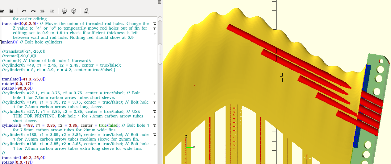
I had to make the internal stabiliser holes longer for experimental use with extremely thick fins.
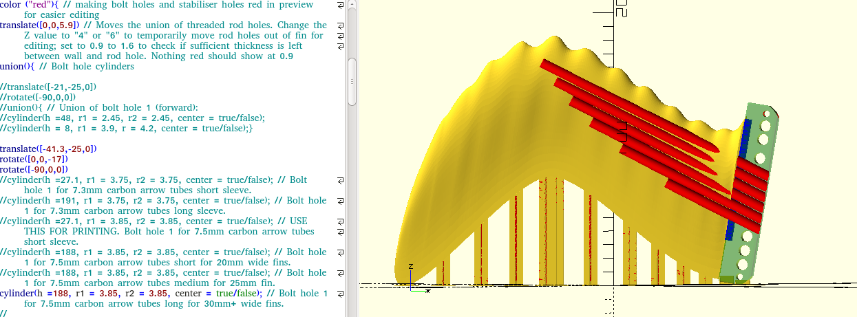
They just don’t touch the sides any longer with a 50mm thick fin, see screenshot.
The “Search and Replace” functions in OpenScad made it very easy to replace all those tiny holes:
internal stabiliser holes made longer for extremely wide fins
cylinder(h=20, r1=0.055, r2=0.055, center=true); old
cylinder(h=200, r1=0.055, r2=0.055, center=true); new
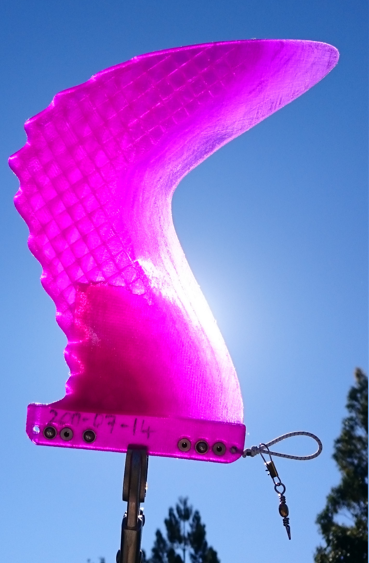
Different curved patterns for fins of different thickness.
The lengths of the red tubes are for measuring the required length of carbon tubes and will not actually be printed with the hollow fins for resin filling.
I’ve tried to create a curved line rather than a straight line through the tips of the rods, I believe it makes it less likely for the fin tip to snap off along that line.
For the thinner 20mm wide version the line is concave, for thicker fins it’s convex.
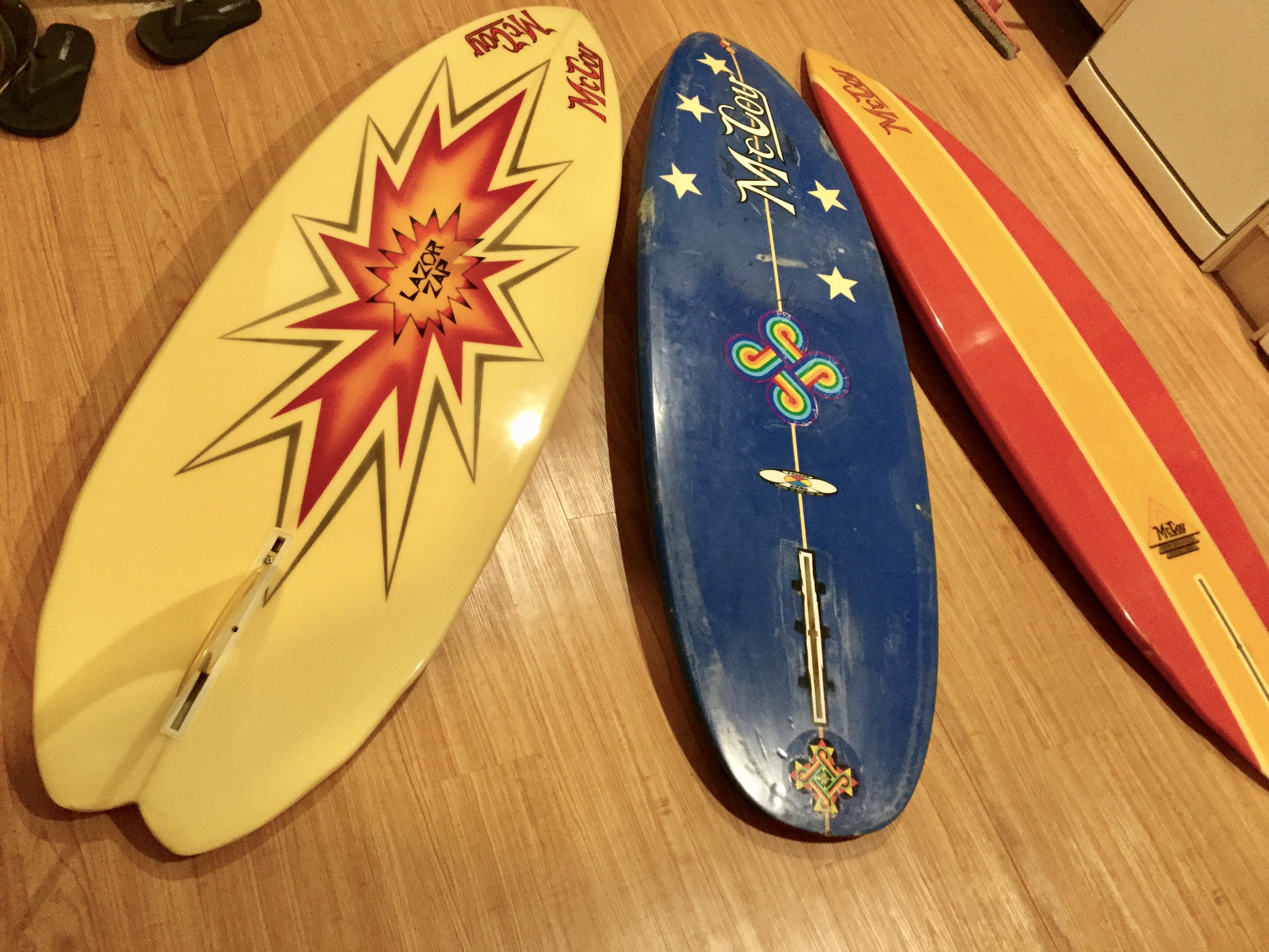
Test surf with printed fin WF2SLEF2226HRx30x0p8mm_UTFB3018infill5pc_X3DtPPLA0p15mm_20170424.gcode went well at Greenmount today.
That is the fin with 5% infill, 6 carbon arrow shafts, and no epoxy resin fill.
It’s the one on the left side in the photo. The one in the middle is the fat one I filled yesterday, it will be next in the surf.
Head high barreling waves, sometimes a bit overhead, the usual crowds (potentially including ex-world champions, current world champions and always many wannabe world champions) made it hard for fellas like me to test a fin all that well. I only got 3 waves in other words.
But, the fin did what fins are supposed to do. I practically only surf 8ft McCoy SIngle Fin Nuggets, with some sort of Gullwing Fin in it. This fin is not spectacularly different from other Gullwing fins, but that’s all I can tell. The level of competition for waves is so intense, that I, who refuses to drop in, gets too few waves.
So, the fin did not hinder my surfing at all; and ‘cause I made it myself it was the bees’ knees etc.
It did not come out of the box one bit, not even when I proned it onto the gently sloping sand bank at considerable speed several times;
and it’s weight increased from 213g to 218g, so I assume 5ml of water got in. I could not see any water levels in the spaces between infill during a quick inspection after the surf.
The 40mm fat smooth fin worked well in it’s first surf at Kirra.
WF2SLEF2226HRx40x0p8mm_UTFB-3-0-1-8_X3DtpPLA_0p15mm_20170430.gcode
I got 2 nice waves in 45min and that’s a good result considering the skilled competition in the near perfect conditions.
The fin did not cause any trouble until it got ripped out of the box and the string attaching it to the fishing swivel snapped. After 10min of searching I found it again, floating around. Inconsistent swell helped finding it, and luck. It’s not a reliable method trying to use the buoyancy of the fin alone to get it back.
The way it got ripped out of the box was such: I found myself caught inside after catching a wave, with a surfer on a head-high wave trying to get barrelled on the wave breaking toward me. A surfer on my left and another on my right less than 5m away were also paddling out toward the breaking wave. I had to turn my board parallel to the wave and jump off, to make space for the surfer on the wave. I could not paddle left or right because of the other surfers on each side. I dove down feet first and let the board cop a KIrra lip broadside. Then the fin was gone and I got another lesson in finless surfing. I’m starting to get the hang of it…
I’ll try stronger string for the next run.
Progressing …
Too many new ideas emerged while trying to write this up, so here is the short version:
Printing the Universal Tough Fin Base at the same time as the fin, from PLA.
Not tested in the surf yet, but feels sturdy in the vise.
Another small improvement to the Universal Tough Fin Base (UTFB):
Recessed screw hole and markers for removing forward section if use with screw is desired.
Due to success printing solid fins (pending more testing in the surf to determine if they snap off), no carbon rods or fill port for resin filling is required, so that I could move the forward ball spring plungers back a bit to make more room for a cutout section.
This fin base can be used in three ways:

Another Sunday spent mostly on this sacred pursuit…
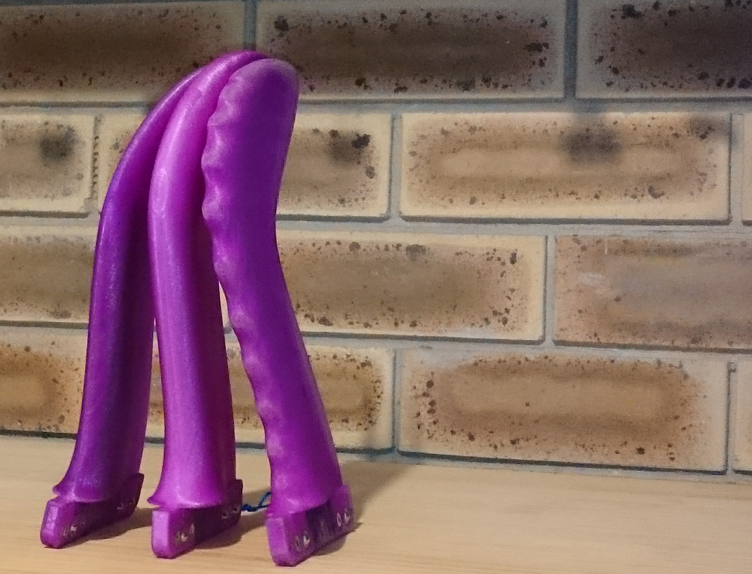
And now I have a few fins ready to be tested by others, for pesky little problems, like:
The blue one is a solid PLA print, I had to sand the surface a bit because the perimeter printing parameters are not quite perfect yet. I think I’ll send that one to wrcsixeight when I also have a solid BLEF version ready to accompany it (soon I hope).
Surffoils can take his pick between the red and the purple fin, and the last one is for a local guy.
Oh wow !
I’d be stoked to ride one of your fins and I’ve got plenty of boards with boxes to test. I’ve got this old McCoy Zap…
That purple ones got my name all over it please !
I’ll PM you now about postage but I can certainly pay for a Priority Postbag to my door.
Thanks very much Mr Mik.
A package is in the mail for Surffoils.
I have put together a set of three fins of similar print settings for you.
This way, you can compare apples with apples, and more importantly, you can taste all the fruit during one feeding frenzy. That’s if you can find a mate or two who are interested in swapping fins in the surf.
.
All three fins have been printed from PLA with a solid ‘UTFB’ and infill of 10% (cubic) above the UTFB.
I have only surfed one of them so far (the red one with winglets), and only once, in weak waves at Burleigh Heads, up to shoulder height, they were not sucky at all.
So there is a chance that the mechanical strength is just not sufficient, and they might snap off. It could also be that the material weakens over time, maybe they break after a certain number of stress events, who knows. It’s all experimental, so use them at your own risk and try to surf them on a few waves away from crowded conditions, at first, just in case they don’t last.
.
I had to sand off the support system after printing the fins, and their surfaces needed sanding a bit, too. So cosmetically they are anything but perfect, and you might find they need more fine sanding attention to detail, in case they hum or whistle dixie or something.
.
All three fins have the same “Universal Tough Fin Base” configuration. Hopefully it will fit snugly into most single fin boxes. It is not the latest version but essentially the same.
.
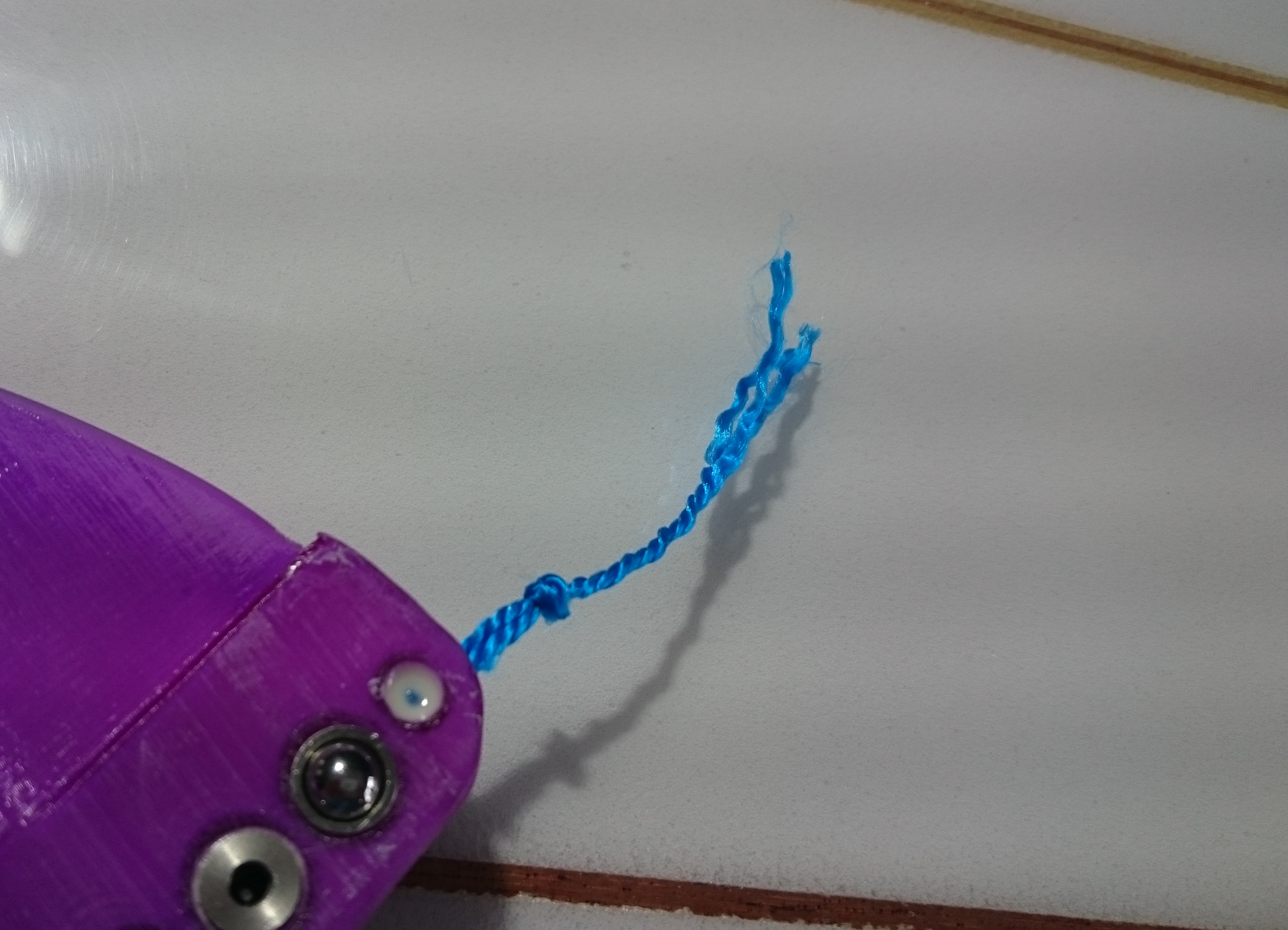
These three fins all sink, so they should be tied into the fin box by screwing a screw and plate with a fishing swivel into one end of the fin box, then attach the fin to the swivel via the stretchy rubber string. I meant to include some more string in the parcel, but just found that I still have it in my pocket…sorry!
So, if you want to use the fins far aft in the box, then attach some sturdy string to the front (through the vertical screw hole) and put the screw and plate in forward in the box.
If the fin is getting knocked out by impact from the front too often (e.g. seaweed), then put a pin in the front horizontal hole.
If you want to screw it in, e.g. once you have found the optimal position, then file off part of the tab fore. You will probably have to remove the fore ball spring plunger for this, but it would contribute very little in this scenario, anyway.
.
I hope you get some joyful rides with these fins.
Please let me know how they hold up, and don’t be too polite, I want to know what’s wrong so I can maybe make them better.