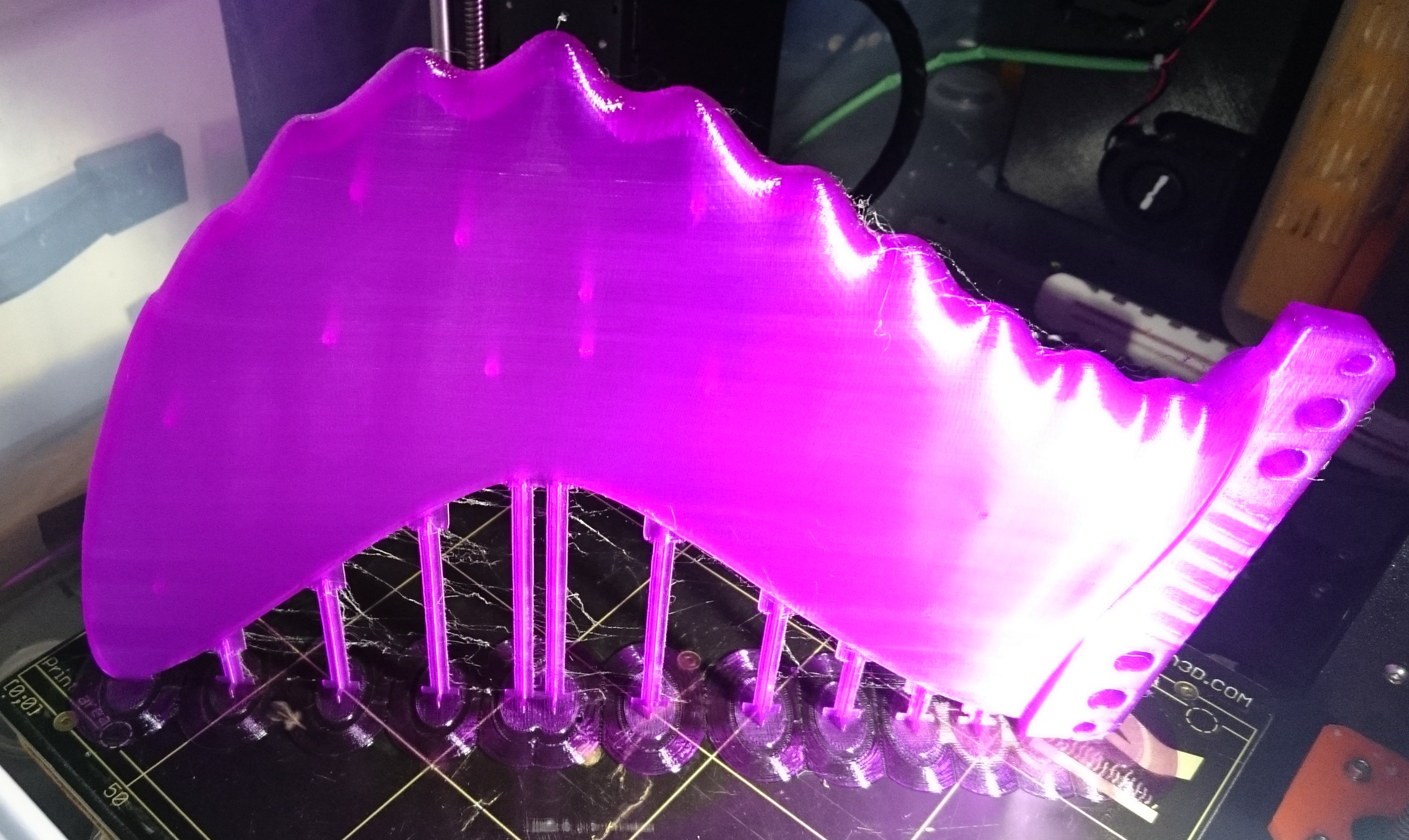
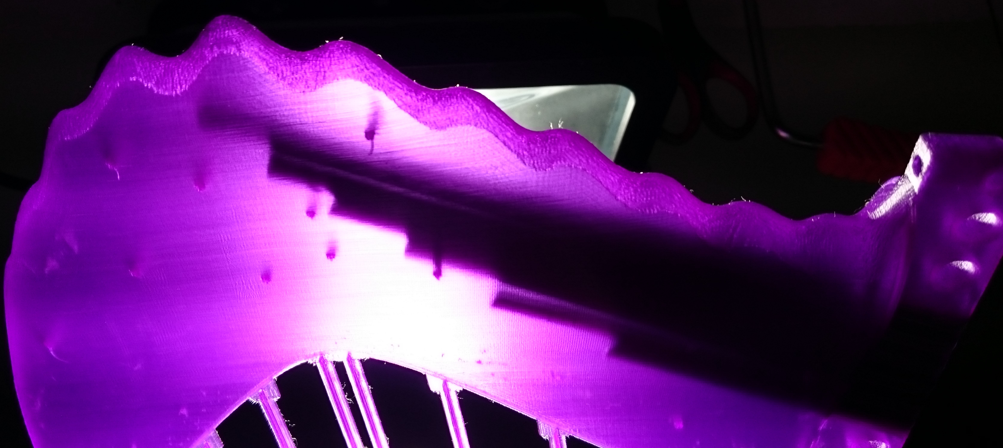
This photo shows the problem (it’s trivial really) much better:
The SS rod can be screwed in to this point without any problems, but then it hits the closed end of the tube. It will just snap the lid off when it is screwed further, but then the pieces fall into the hollow fin and are a little pain to remove through the other hole I need to make, the one for filling in the liquid resin.
If a hole is made (in CAD software) in the solid object, then the entire hollow space on the inside needs to be defined.
I think this is a really difficult CAD problem, at least for my low level of expertise, particularly when it comes to the fin base (with all the BSP holes) and the connection of the fin base to the fin. If I define the fin as hollow in OpenScad, then there will be a printed layer of plastic around the entire outside of the fin tab, including where it touches the fin. Therefore there would be no continuity of the resin at the most important point, where the fins tend to snap off just above the box.
I reckon I better give up on this one. The low tech solution is to use a 4mm drill bit for the 5mm SS rod holes, a 5mm drill bit for the 6mm SS rod holes, and a 6mm drill bit for opening up the hole for filling it with resin. Then rattle the fin around until all plastic fragments have fallen out of the resin filling hole.

I adjusted a bunch of things while preparing a file for use with carbon arrow tubes.
The fin tab is shorter so that the fin can be more forward while surfing.
I lowered the position of the lowest BSPs by 0.5mm and placed all of them on that same line, while reducing their number from 6 to 4.
The fit in the boxes is so good that I really don’t need BSPs to stop the fin from wobbling in the box. I just need them to stop the fin from coming out, and that works best if/when the BSP balls are fully extended into the groove at the bottom of the box.
I added the screw hole back in, in case I want to use that option.
Pin holes remain fore and aft in the base, in case they come in handy.
Bottom corners of fin tab rounded off so it actually goes in the box if a pin is inserted.
Internal stabiliser positions have been adjusted to keep them away from where the carbon rods will be inserted.
Changed the resize of the finFoil.slt file from resize([0,240,0],auto=true) to the actual resize([0,238.9,0],auto=true)
X-beam support lengths adjusted a bit to accommodate the slightly smaller fin size from above.
Still needed are small tweaks to minimise waste of material for printing of support structures that are higher than needed (due to rounding of tab base corners, there are now 12 superfluous layers (at 0.15mm) of supports) and the supports are probably also stronger than needed.
But first, I have to repair the printer again. The fin printing tends to break the cables, because the extruder needs to move to the extreme x and y positions for most of the layers. Temperature sensor cables and nozzle fan cables are shoddy again and make intermittent contact. Grrrrrr…
Picture shows internal stabiliser holes (enlarged for editing) and projected carbon rod locations and lengths.

It will be interesting to see how the carbon tubes work out.
I printed one fin for use with carbon arrow left-overs so far.
It turns out sonme of the broken arrows are 7.3mm thick, some 7.5mm. Lucky me, because the smaller ones fit in this fin.
However, I want to use the larger diameter arrows, because the weaker ones were from arrows made for a child’s bow, while the 7.5mm version is suited for use in powerful compound bows that I can barely draw.
.
So, another day of concentrated effort has gone into refining this project, and now I have an OpenScad file that has a (hopefully) functional set of 5 carbon fiber rod guides that will work with my Gullwing fins of the 20mm and 40mm width variety, with BLEF or smooth leading edge. The carbon rods could be a lot longer for thicker fins and for smooth leading edge fins, but I figure I’ll try to use the same carbon rod configuration in all of them. The thicker fins should be stronger anyway due to more resin fill, so if the thin fins are OK with short rods, then the thick fins should also be OK.


The support system is much improved (I hope), using less material. The currently running print might show if it still has the required strength.

cool! love the styrofoam balls idea for the core!
The print went well, except for ongoing issues with breaking cables.
The fin printed weighs 85g in total, including all support structures.
After removing the supports, and drilling the holes for the carbon shafts out, and a hole to fill in the resin, and shaking out all the leftovers inside the fin, it weighs 75g.
100 -(75g/85g*100) = 11.76% material waste. And that is PLA, renewable and biodegradable, and no dust created and inhaled during sanding. The micro-particles possibly released into the air by the 3D printing process may be an issue.
There will be very little waste from the carbon fiber rods, or stainless steel rods, to reinforce the fin, and whatever resin is poured in can be measured quite exactly to prevent wastage.
A potential concern remains: With thicker fins, and particularly in a hot environment, the resin could get so hot inside the fin that it changes shape while the resin goes off. Temperature control might be essential when filling thicker PLA fins with resin.

I worked out how I can change the thickness of the fin without messing up the rest of it, without having to bother finFoil for another high resolution rendered STL file:
Previously I used this command in OpenScad to enlarge the finFoil.stl files:
resize([0,238.9,0],auto=true)
This works for the various Wanderfalke fins, because their Y-axis height is set to 238.9mm in finFoil. The “auto=true” part of the command adjusts the value for the zeros in X and Z position so that the proportions remain unchanged.
With much fiddling I found that the command
resize([199.2545,238.9,20])
works for Wanderfalke_2_1_6_5_HR.stl and 2-1-6-3HR.stl in such a way that nothing changes at all. But now I can change the Z-value for thickness and the X and Y dimensions remain unchanged. Same fin, different thickness, perfect for testing where the sweet spot for the thickness is, or for what thickness works best in which conditions (board size, wave type, wave size, surfing style, etc).
The command
resize([0,238.9,0],auto=true)
can be left active in the OpenScad code, because a later “resize” command overrides it.
Just activate the desired “resize” command just above the “import()stl” command and change the Z-value to change the thickness.
A slightly different command is required for the smooth leading edge Wanderfalke fins because of the shorter cord length:
//resize([196.065,238.9,30]) // for Wanderfalke_2_2_2_6and7_HR.stl
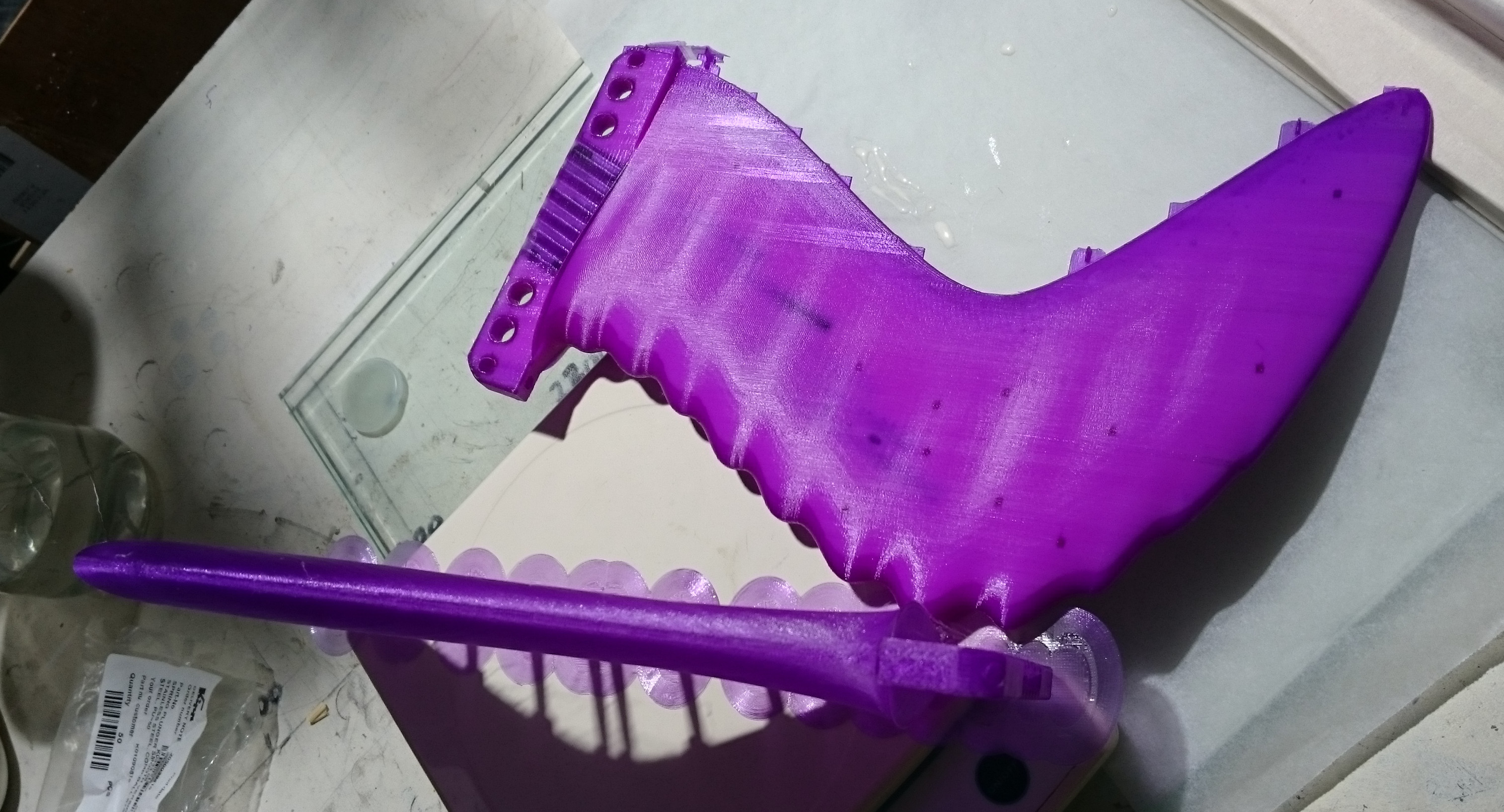
Below are picture sof a 30mm wide BLEF Wanderfalke fin. I hope I get carbon rods and resin into it later today.

I’m sure you said somewhere, many pages back. What type resin are you using to fill the fin?
Have you tried casting resin?
Adding a filler to the resin may help lower heat generation and strengthen the cured resin? Duuuude used “cotton flock (flox)” in epoxy resin to mold his own fin plugs/boxes. End result will be more opaque rather than crystal clear. The Duuuude home-made fin plug/box thread is at this link (pictures are gone now):
http://www.swaylocks.com/forums/my-own-finboxes
When filling your printed fin shells with resin or a resin-fill mix, maybe a gentle vibration, like that from a Whisper aquarium air pump, would help the resin to settle into the hollow fin core better:
Oneula wrote:
http://www.swaylocks.com/comment/456101#comment-456101
“Anyway Charlie said they would buy the really small aquarium pumps and put them on their glassing racks for glossing boards. The very slight vibration on the glossing racks would assist the final coat to smooth out to get that perfect glass finish…
A pretty elegant and simple idea to solve a common headache”
The carbon rods for one 30mm wide fin weigh 18g; with hot glue plugging both ends, they weigh 20.3g. For a little while, I was considering using something that will stop the resin from entering, but will later dissolve in water, like Gummibaers (or some other sugar/gelatine mix). I have not tried this, and for 2.3g weight saving, it’s not worth it.
I made up a set of templates and 2 sets to be put in fins. Enough broken arrows left to make a third fin, so I can make 4 fins (if I use the templates) before I need to go shoot something to break more arrows.
https://swaylocks7stage.s3.us-east-2.amazonaws.com/s3fs-public/DSC_0081_templates+2sets.JPG
The epoxy resin I use is West 105 + 207. For no really good reason, other than they have a factory not to far away and I can buy more any time I need it. I don’t think it is the best resin for the purpose. There are probably stronger ones, and other formulations that don’t get soft as early as this one when left in a hot car. The 207 hardener is a little better regarding clarity and UV resistance than the other West epoxy resins, but they stress at every opportunity that you must paint the epoxy to protect it from the sun etc etc.
Maybe all or most epoxy resins are like that, I will research that at a later time when I have figured out the more difficult aspects of this whole fin-making adventure.
So, I decided to use the same amount of West 105 and 207 (93ml + 31ml) that I used for the 20mm wide fins, but add in qcel. I just add in about the same volume qcel as West 105, mix them (against everyones advice, but it is much better to mix the qcel and part A first, then add in the hardener. The manufacturer says you should never do that, but it works much better that way).
Filing the holes open so the carbon rods fit in was a bit of a mission, but eventually I managed to insert them, hammering them in actually. Gently, but with a hammer.
Due to the thickness of the qcel resin mix, there were no leaks out of the internal stabiliser holes or anywhere else.
Getting the bubbles to rise in the qcel mix is a lot harder than with straight resin. For simpler fin shapes, and maybe without rod inserts, a vibrator of sorts might help to get the bubbles out, but for this fin, it’s about an hour of manually rotating it to all sorts of angle to maneuver the bubbles around towards the exit.

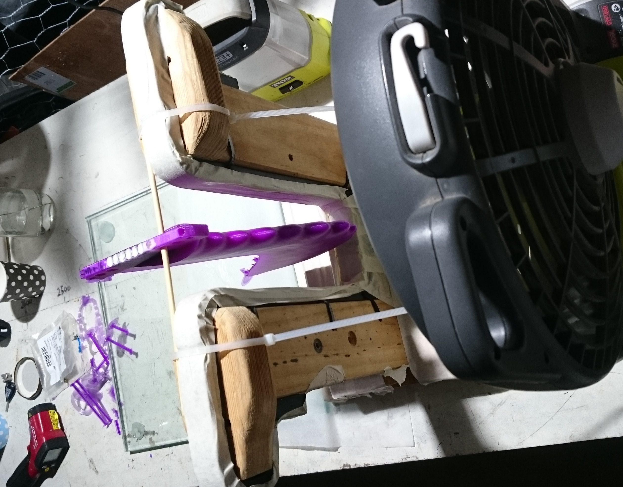
When the surface temperature of the fin got to 44degC, I figured better safe than sorry and turned a fan on it. That brought it down to ambient 25C very soon.
The surfboard repair stands I built earlier work very well to hold the fins while they are being filled with resin.

I have not used any ‘neat’ resin without qcel for this fin at all. During earlier casting experiments, I used qcel for the lower parts of the fin, and neat resin for the tab and adjoining part of the fin. You have to get the timing right and pour the heavier neat resin when the qcel mix has set enough, or the neat resin will sink into the fin tip and you get a tab full of weak qcel resin.
Anyway, I think that 6 carbon arrow shafts will be strong enough so the resin is not needed in the tab.
And I’m pretty certain this fin will float!
It’s smooth edged twin is printing at them moment, with a further evolved fin base. Using different print settings, I hope to keep open enough space for the resin to get around 6 instead of 4 BSPs in the base. It should also print faster, use less material and look better.
Hope it does not leak resin like a sieve…
You can get the OpenScad code at this link: http://shop.prusa3d.com/forum/print-tips-slic3r-settings-kisslicer-model-repair--f12/printing-a-large-surfboard-fin-t2675-s60.html?sid=b4cc392ac9eb891f753a568667c07849#p30336
It’s to cumbersome to post on Swaylocks without the “code” option.

The resin fill went well and lil’ brother has finished printing.
Print time now down to 11h 13min, using 80g of filament.

Why Qcell? That would weaken resin strength.
Cotton flock should actually improve strength with the small cellulose and lignin fibers. Cotton flock should weigh less than milled FG fiber – specific gravity 1.54 vs. 2.58.
Duuuude’s molded fin plugs/bases were most impressive (shame the pictures are gone).
stoneburner wrote:“Why Qcell? That would weaken resin strength.
Cotton flock should actually improve strength with the small cellulose and lignin fibers. Cotton flock should weigh less than milled FG fiber – specific gravity 1.54 vs. 2.58.
Duuuude’s molded fin plugs/bases were most impressive (shame the pictures are gone).”
I tried using silk for this purpose somewhere earlier in this thread. I never tried if it makes the resulting fin float, need to look through my records, dig up the fin and test that.
However, forget injecting silk (and I assume that’s going to be the same for cotton) laden resin into the fins the way I make them at the moment. It would never flow through the syringe. I used a 20ml plastic syringe with blunt SS needle about 60mm long. That way I can get the resin+qcel mix past the narrow spot between the BSP holes in the base before it goes off. A fridge is required to control the pot temperature down to 5degC or so, because the resin shrinks as it sets and you need to top it up many times.
Fibres (compared to qcel balls) make the mix to viscous to get it into the fin shell.
And the fin floats! Heureka!
Next up: Another attempt to just print in PLA, this time using infill, then insert carbon rods, no resin. It might be strong enough due to the rods.
Duuuude mixed and “poured” his flock-resin mix into his molds. The mixture looked homogeneous to me. He posted his “customized mix ratio” in the thread I linked. Cannot say how well it will flow through a syringe.
The cotton fiber (flock) is very fine ground.
Duuuude’s mix ratio:
http://www.swaylocks.com/comment/407369#comment-407369
“one finbox is made from 25g epoxy resin + 10g hardener + 4g of pigment + approx. 3-5g cotton fluffs that make it easy to sand (way better than other well known finplugs) and supports the thread’s durability.”
This fin was printed from PLA and then I hammered in carbon tubes. No resin at all.
It feels solid but has not been surfed yet.
Total weight 238g. It floats well.
I’m not putting in BSPs, it seems to be stuck in the box good and proper without them. If it gets too thin with repeated use, I can still add the BSPs in later.
A original gullwing fin (fibreglass and resin) weighs 310g and is much thinner.
The same fin filled with Q-cel epoxy resin weighs 8g less, but there is much room for making the resinless fin lighter and cheaper by reducing the infill density. Eventually it might become to weak, but most of the strength is in the carbon rods onyway.
Material costs for the fin: AU$7.50 for PLA filament; about AU$15.- for carbon rods; less than AU$1.- electricity; and lots of printer time. I had to stop the printer several times because I do not want to run it while I’m away, and this print takes several days. Overall it took 54hrs 20min to finish the print, including long breaks.
The fin has imperfections because the printer is not working 100% correctly at the moment(cables half-broken again). I hope the 0.15mm layer shift and a blob will not happen next time.
The fin looks close enough to what I want to take it surfing. It may not perform as well as a perfect print might, but I think the strength test (by surfing) will be giving the same results as a perfect print would.

That amazing Mr Mik ! So much progress and innovation.
Can I buy one please ?