Regarding OpenScad programming: It looks more difficult than it really is, but It gives you complete control.
I only use it at a beginner level, the most complicated command used is probably the Minkowski function to round the edges of the fin tab.
Much of it is copy and paste.
Stuff like rotating the entire fin by fractions of a degree until it fits into the print volume of the printer would be very tricky without OpenScad.
The fin uses the entire printable range of the Prusa i3 MK2 (250x210x200mm), to the last millimeter.
I have not used Autodesk123d, but it looks like it’s used more for artistic expression than for engineering, going by the pictures on their website.
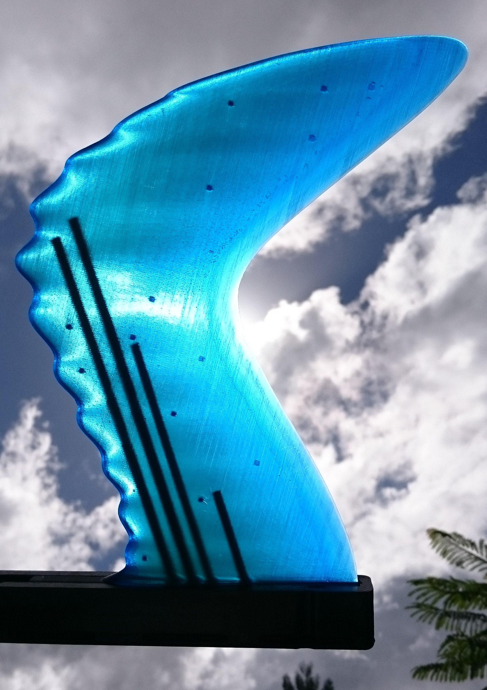
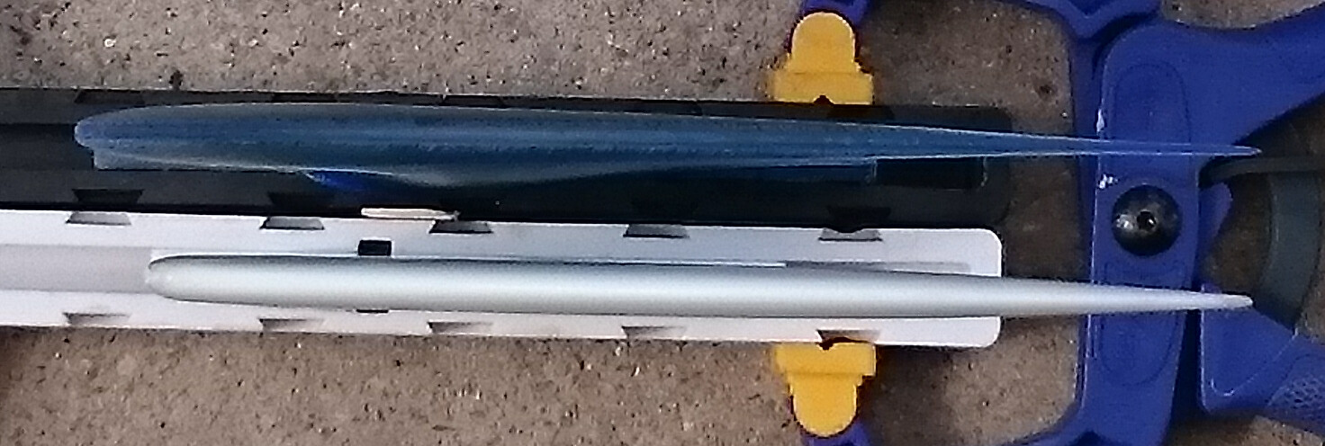
The stainless steel rods are 6mmx200mm, 6mmx190mm, 5mmx140mm and 5mmx70mm and weigh 93g. They need to be placed carefully so that they do not interfere with the holes for the ball spring plungers.
The entire fin weighs 317g (approximately 93g stainless steel, 140g epoxy resin, 84g PLA)
To fill the fin, I drill a hole and use a 25ml syringe. West epoxy 105 x 93ml and 207 x 31ml is required with less than 5ml left over at the end.
A fridge is needed to keep the resin in the pot cold, it takes 1-2 hrs to fill the fin and remove air bubbles and wipe off spillage through the internal stabiliser holes. The resin seems to shrink as it sets, and topping up repeatedly is required for several hours.

Link to the finFoil file:
http://finfoil.io/s/3D/mz45guzq6u1dg3bwesqy3ucggest7baq
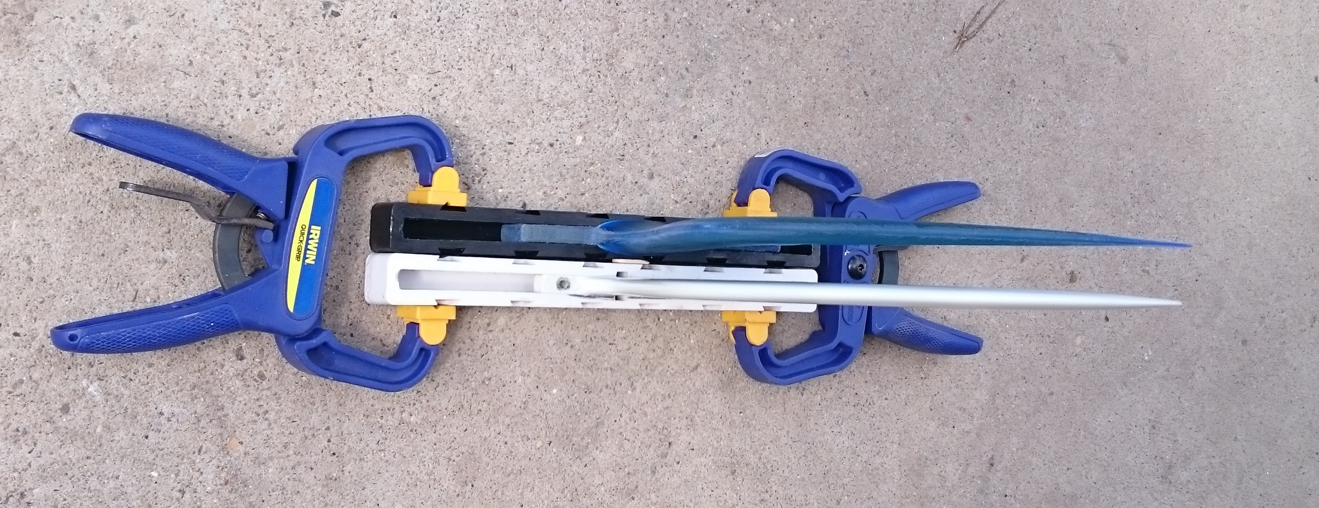
Sanding the trailing edge takes an hour or so, needs to be done under water because the PLA just melts when sanded dry.

My head is spinning but I’m still reading. Carry on.
In order to hang on to the snap-in and out system when hit from front or back, I resorted to a low-tech fix: A fin screw and plate holds a piece of string in the fin box, and a fishing swivel quick release is tied to each fin.
The weight of the fins is very similar to the weight of an original McCoy Gullwing fin, it sinks like a rock.
One day I might start another effort to make a floating fin, but for now I shall go surfing more often and read more about what others are up to on Swaylocks.

Destructive testing went well as far as I can tell.
The epoxy resin and the PLA crack at the fin base when I pull hard enough, but it does not snap off.
The tip does not seem to want to break off before the base gives up, so hopefully I got the length of the steel rods about right.
The fins have a little more flex than the fiberglass version.


AH You are building hollow and filling the fins with resin…Brilliant! Carry on then! I need to read more and look at pictures less…
I see what you mean on the skinning…still I woulda knocked that shelf off your design and just add another composite layer or 2 there for strength/stiffness.
regardless you have a solution that’s working and a sick looking fin, there’s multiple solutions to every problem, nothing wrong with yours
Love what can be done/you are doing with the print to get around the initial material weakness. Good stuff! they look fantastic.
Love the determination on this thread to…
Regarding 123d, it’s kinda painful to work with but there are good online tutorials. things can be built to dimension so it’s not just crafty but can do some real cad work.
It has random errors and crashes and brain farts, so you know it’s s free program.
I haven’t played with opens cad but 123d is a little closer to the graphical Autocad programs I used to use professionsally (like 20 years ago)
I’d say google sketch up has it beat in many areas but 123d seems to more often be able to do what I want.
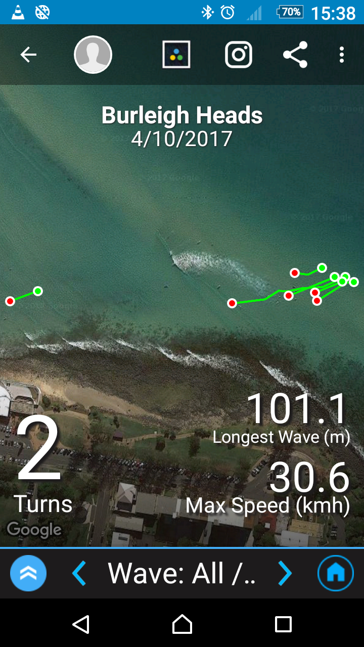
I have surfed the fin with bumpy leading edge at Burleigh Heads today and it went well.
Well, not well as far as my surfing is concerned, I was definitely not in the zone, and I’m not a good surfer at the best of times, but the fin did not fall out of the box and did not suffer any damage.
A number of wipeouts were involved, too.
Waves had about 1.5m faces with a cross-shore wind.
All I can say so far is that there is nothing spectacularly wrong with the fin, and that I think I need to shorten the forward part of the base so I can place it further forward in the box.

Mr Mik, I am so impressed with your tenactity and ingenuity with the cad and all aspects of your fin. Do you find the rod length and placement affect the flex pattern ?
What GPS system are you using to get the above information and image ?
Did you get the internal rod idea from Stoneburner ? I remember he suggested it 7 months ?

Yes, Stoneburner suggested the above concept 7 months ago, and it included rods, but I have never really understood what exactly he meant. I think I paid very little attention to it at the time, because I had just ordered the 3D printer and was hell-bent on fixing my own CAD illiteracy. And the concept Stoneburner described does not get around my central problem with foiling a fin: That the last few shaping / sanding moves can easily ruin it, and the result is always different between fins.
Also, 7 months ago I was still hoping to make a fin that floats, so that I can find it again if it comes out of the fin box in the water, thus making it safer because the pin-less BSP system allows it to come out of the box no matter from what angle you fall on it in a wipeout. And I still don’t know what FG rods are, although I just googled it half-heartely, but twice.
But Stoneburners ‘carbon or FG rod’ suggestion just reminded me of all the broken carbon arrow shafts that I kept. I cut off the damaged parts when they shattered (my bow shooting is about as hapless as my surfing!), and kept all the pieces although they are too short to make arrows. I just knew that these high-tech and expensive, amazingly strong pieces of gear will find another use some time later.
So, thank you Stoneburner, I’ll try hollow carbon fibre arrow shafts next. I might have to develop that wider fin box first, I think the arrows might be too thick for a standard single fin box, I’ll measure them once I’m finished typing this.
Don’t you love how this collaborative stuff works? ![]()
Regarding the flex: The stainless steel rods must certainly affect the flex pattern. I have not filled an otherwise identical PLA printed shell with resin only (without SS rods), but I have done semi-destructive testing attempts on fins with hardened steel bolts instead of SS rods. The hardened steel bolt fin did not snap off at the base either, and the tip of the fin did not snap off above the end of the bolts, although they are much shorter than the SS rods I used.
So I think there is every possibility that the rods (or hollow carbon shafts) could be made shorter and still prevent snapping.
I did try to design the rod length so that their ends form a curved rather than straight line, to prevent provoking a fracture line for the fin tip (without rods) to come off the rest of the fin. If the second rod was not longer than the first, the tip would snap off much more easily, I believe.
Problems with the hardened steel bolts include:
- high price
- rust very easily
- thick head is hard to fit into the 9.2mm fin base.
- only available in relatively short lengths.
The length and thickness of the SS rods in the fins that I have made so far is simply the longest and thickest rod that I could fit into the fin, without blemishing or breaking the 3D printed surface. It took quite a few hours of fiddling around to get it right, but most of that time was spent learning how to do that. An experience OpenScad designer could do it much faster, and anyone can use my published OpenScad code to relatively easily adjust it to different fins. I’ll try to improve the code annotations if/when i get around to it. The SS rods can only be a couple of mm longer, if that, and thicker by only a fraction of a mm, before they would break the surface of the fin or interfere with the location of the BSP holes.
That gizmo I use for the GPS and acceleration data collection is called ‘Trace’.
Now I’m off to measure the arrow shafts…
Here is a link to a post with a picture of one of the intermediate steps with hardened steel rods. I did much of the development with help from a 3D printing forum.
http://shop.prusa3d.com/forum/print-tips-slic3r-settings-kisslicer-model-repair--f12/printing-a-large-surfboard-fin-t2675-s40.html#p28652
Carbon arrow shafts turn out to be 7.5mm diameter and could therefore be trialled even in a fin made for a 9.2mm wide single fin box. BINGO!
They are so freakishly light that the floating fin phantom is beginning to haunt me again…
Have you thought of tapered CF tubes ? To factor in the thinning base to tip ? I’m sure you’ve got the skills to wrap and vacbagging a few layers around a sanded chopstick ?
You’ve got a great field of experimentation and wide skills to explore in any direction, it’s like watching a new technology being created. Just brilliant work !
You’ve prolly already considered this but could you incorporate printing the ‘tubes’ or similar internal structures for printing stability of the fin ?
It would slow the warpage and allow you to seperate regions for resin / carbon fill.
Looking good MrMik!
I want to say that Stoney is using FG as an abbreviation for Fiber Glass.
The arrow shafts sound great. Less weight with lots of strength. If you capped them they would hold air and reduce the amount and weight of the resin fill, getting you closer to floating. You could also try adding some foam rods or bits to take up some of the volume of resin in an effort to loose weight and gain float for the fin.
FG = FiberGlass. Jrandy is correct.
In the post Brett mentioned, the rods are in a center layer/core used for making a fin with outer wood surfaces. The rods are for strengthening the fin and base. And yes the wood surfaces need to be foiled.
However, that same internal rod concept is intended for a resin-based fin also.
BTW when I was looking at carbon (C) and fiberglass (FG) rods, I looked for suppliers of C and FG tubes also. As I recall, the rods were a lot less expensive.
Pretty sure the suppliers carried C tubes in several diameters.
I also remember seeing tapered C tubes for making fishing rods. (I like the tapered tube idea Brett)
Thanks everyone, my head is spinning with all these great ideas!
I knew I should not have thrown that broken telescopic fishing rod away, it would come in so handy now with all the different diameter carbon pieces.
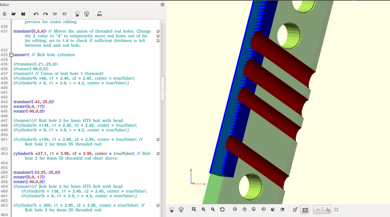
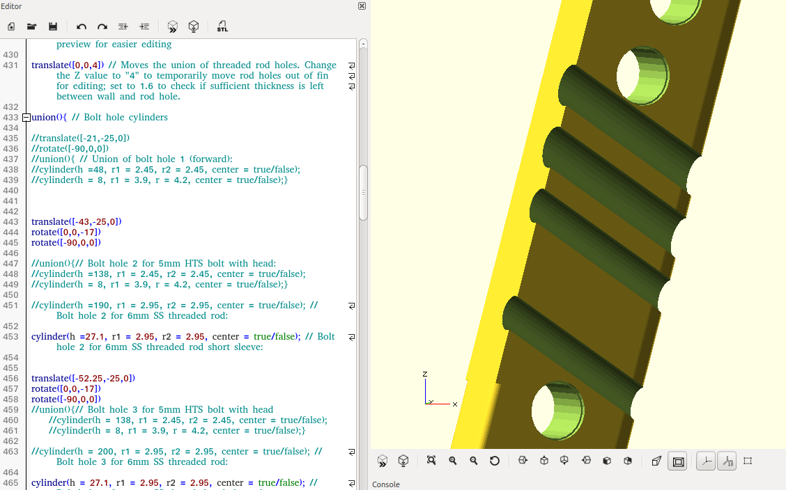
For today I hope to achieve one little thing bugging me, and that is that I want the rod holes to be open. So far I had to drill each hole open after printing the fins, so that the SS rods can be screwed in. Their entry into the fin box is open, but then they are closed at the top of the fin tab. It feels like it’s a word on the tip of my tongue, any moment now it should pop out…
Integrating rods during printing will not work with this type of 3D printing, there must no be anything sticking out above the last layer that has been printed, or the printhead will hit it.
I don’t have a vacuum setup, but I got close to buying one a couple of times, it’s such a fabulous tool, using all the weight of the atmosphere abave use to squish stuff together evenly from all sides. And the de-gassing of resins and mould making materials to get the bubbles out, that’s so tempting too. I did try to rig up an old car tire inflation pump as vacuum pump, but it’s not strong enough for de-gassing silicone before casting. Anyway, that’s for other threads, I know there are many on Swaylocks and I will undoubtedly eventually start mucking around with vacuum pumps.
With 3-D printing, seems like you could pre-print the tube tunnels into the fin. Then slide the tubes into the printed open tunnels.
“With 3-D printing, seems like you could pre-print the tube tunnels into the fin. Then slide the tubes into the printed open tunnels.”
That’s what I’m doing already. It’s a bit hard to explain.
The tubes are there for insertion of the rods, but they end with a solid lid on the tube. It is because the OpenScad and Slicer software sees the whole thing as a solid object, but only calculates it’s surface. When you ‘difference’ an object like the cylinders for the rods from the whole thing, then the surface of the whole thing is closed where the differenced cylinder ends.
I’m trying to make the whole fin hollow at the moment, but causes all sorts of other problems and is tricky to do.