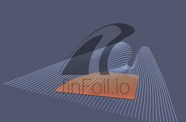
I’ve been playing with some different simulation techniques and found these images quite interesting.
Enjoy!
https://twitter.com/finfoil/status/869457681588912128


I’ve been playing with some different simulation techniques and found these images quite interesting.
Enjoy!
https://twitter.com/finfoil/status/869457681588912128
Obviously less turbulence with the square, but what about drag?
I am no fluid dynamics expert. But it looks like less turbulence with the elliptical foil – no trailing vortices.
I thought one of the advantages of the elliptical wing on the British WWII Supermarine Spitfire was less induced drag.
Hans, I was going to ask if you could use your Finfoil expertise towards developing a Hydrofoil ?
@ Surffoils
Technically a fin is a hydrofoil.
Hydrofoils (as the term is used in surfing) and fis are both low Mach and high Froude number lifting bodies with similar Reynolds numbers.
The high Froude number and similar Reynolds numbers mean that the flow around horizontal hydrofoils and vertical fins behaves similar.
Therefore, learnings from fins apply to hydrofoils too.
@phebus & stoneburner
The voriticity you see in the images is not real turbulence.
But you are correct in assuming this high vorticity leads to higher turbulence.
Induced drag is drag resulting from energy dissipated in the turbulent wake, so higher turbulence in the wake leads to higher drag.
The total drag is the sum of the induced drag (form drag) and skin friction drag.
Beware, these images do not prove anything, I’ve just been experimenting with different flow calculation techniques that make different assumptions and simplifications about the flow field.
But I thought these images were interesting enough to share and start a discussion.
Hans , I’ve gotten really good results with longitudinal or Linear foils, are you able to do images with aspect ratios of <1 ?
So you mean a picture of a square low AR foil?
Like the first one, but with AR < 1 ?
Yes Hans, exactly that, if the first one has an AR of 10 then I would be interested in seeing an image of potential flow would look for a foil with an AR of . 1
10 times the chord length for the width please if it’s possible ?
That looks very interesting, Hans.
Can you run this program on any of the finFoil files in the index?
If so, could you program a ‘bot’ to use spare processor time to mill through all the files made by the users of finFoil, to find the interesting ones?
And, could you compare the effects of winglets vs tubercles on otherwise identical wings/fins with this software?
I could try to concoct some wing shapes if you are happy to run them through this.
@Surffoils
Here is a low aspect ratio foil span/chord = 1/5, the first pic was 5/1.
Why do you assume these to be potential flow solutions?
@MrMik
I could run this on all fins indeed.
However, there is no best fin criterium.
Please understand that I don’t claim these simulations to be accurate flow solutions!
I’m just experimenting with different simulation techniques and models to figure out which ones would be interesting enough to integrate in finfoil.
While doing so, I came across the interesting images I posted and couldn’t resist sharing them.
Thank you Hans, I think we all enjoy seeing a representation of the flow.
Can you play with the AOA on those foils. The elliptical shape theoretically provides a more equal lift distribution, but also has some nasty effects at high AOA and unexpected spanwise stalling.
It’s really interesting to see how the tip vortices affect drag. Airplanes have come up with a lot of novel solutions to try and solve that problem. There are ways to optimize for lift and drag by taking advantage of it.
Can you model with the foil against a flat plat? I’d be curious to see the flow interations there.
Very cool stuff. It’d be cool to baseline some actual fins on an FEA software to get some basic numbers to compare apples to apples.
I’m still really curious about thick fins vs. thin fins.
Yes you are right about elliptic outlines having other issues.
Those pictures do not prove anything, they just illustrate how the vortices of the elliptic outline are distributed over the foil instead of localized at the tips.
The flow around foils is very complex and extremely expensive to fully model.
Therefore simplifications are made with almost all numerical simulations and therefore only produce sensible results in limited ranges and under specific conditions.
I’ve been studying fin hydrodynamics for a while (holding an Msc. degree in aerodynamics) and I am compiling a set of calculation methods that allow better design of fins and other low Mach number lifting bodies.
Unlike some marketing likes you to believe, just some colorful simulations lead you nowhere.
The tools I’m developing help you with more than just reducing drag, like you correctly highlight stall characteristics are extremely important but very hard to model correctly.
This will take me a couple of years to go public, because my spare time is limited and also distributed across different more lucrative projects.
So please understand that I do not wish to disclose which calculation methods I’m using just yet.
I can only say it includes FVM and FEA but is not limited to it.
Of course I’m always available for business opportunities, that might help speeding up the development.
One point seems important to me: in the first picture, the end of the wing stays exactly the same thickness as the rest of the wing. It’s abruptly cut, so to speak, whereas in the second picture, the end of the wing seems to taper to zero thickness.
Very good remark balsa!
That has indeed a big influence on the localization of the vortex on the wing tips.
With every change in profile section, the change of circulation on the wing (=lift generation) is shed into the wake as vorticity.
And because the first foil has a constant profile, all vorticity is shed into the wake at the wing tips.
Hans, your works sounds very interesting. I get a laugh out of seeing the top pros designing fins. Granted, much of what we have learned in surfboard design has been trial and error. But I do think there is much more than can be done with fins.
All the best
Thanks Greg!
I believe trail and error is in the end the only way to design fins.
However, good understanding of the physics and effects that cause certain behaviors reduces the amount of needed iterations significantly.
I’m certain that decades worth of experience in trail and error might even be more efficient than understanding the physics.
But transferring that experience to others is extremely time consuming.
I see these numerical methods as an accelerator in fin design, not as a replacement of trail and error.
Very well stated, Hans.
we already know that a sharp, defined point reduces drag, right? we saw that in the firewire model which compared round rails to sharp rails. a different scale but the same kind of thing, I thought
In a sense a winglet is similar to a tubicule, only terminating the tip rather than the leading edge.
confused yet?
The sharpness of the trailing edge is not that important.
At some point on the profile, the flow will separate, the geometry behind that point is quite irrelevant.
More concrete this means that if your foil’s wake is 1mm thick, there is no reason to make the trailing edge sharper.
You cannot compare planing and submersed body hydrodynamics, they are very different.