Is there any chance of STP (object) 3D export in addition to STL (mesh) export? I use Fusion 360, not sure if anyone else does, but it’s a great free CAD/CAM program. The only issue is I can’t generate g code from a mesh. So if STP export is a possibility, that would be awesome! (I don’t know how hard it is to export STL vs STP…maybe it’s not a possibility)
Hi canman,
You’re not the first to ask this.
It is definately possible to implement this, however I have other priorities. You might have noticed that others can generate g-code from STL files using free tools. Maybe jrandy can help you here.
If you really need STEP export, feel free to make me an offer to implement it. But I won’t put time in it for free, because I don’t need it.
Kind regards,
Hans
Nah, I can make the STL format work, I was just curious. There are plenty of programs to conver the mesh to solid as you mentioned, no worries brother. Very cool program for sure!
I poured the molds yesterday.
First I was going to just do epoxy but figured I’d need some cloth to prevent basic cracking. Then the idea of adding carbon fiber seemed fun too. So I cut a piece of 7.5oz plain weave and a patch of 3k CF from scraps. The cloth was cut by using spray adhesive and a tissue pattern and a sharp scissors. The adhesive would not release from the carbon so the tissue ended up in the fin.
I coated the mold with resin, added the cloth, more resin, carbon fiber, and filled the mold. I estimated 35ml each but noticed earlier that some spots were deeper than the original design. I mixed 90ml and that barely filled the mold after brush loss and a couple grams to glue two mismade sides into a center fin. I didn’t want to make another batch so I let it ride. The mold was just filled, not heaped.
Resin is Resin Research Kwik Kick. I waited 3 hours and pulled them out. They were still pliable so I put them on a board with foam and weights to keep them flat. Some of my cloth poked up through the open top and made a mess of the trailing edges. Filling the mold heaped with resin with a layer of cloth and a top plate would have made a stronger and flatter fin.
The resin is faithful at reproducing the mold- every bump, dip, scratch, and tool mark. I had some bubbles too. I think I would need a closed mold and infusion to use cloth as reinforcement, to remove bubbles and keep the fibers ‘inside’ the fin. I might try some resin with milled/cut fibers under a plate and see how that goes. Without the cloth or fibers the resin seems brittle on the tip and trailing edge. My previous mold was 2-sided with a thicker design so the result did not seem brittle. The cutting board material does not bond to epoxy, so no PVA or wax required as a mold release.
There are probably some other things I could do better too: finer tooling passes, somehow sanding/graining the mold, drafting the side walls, allowing the parts to fully cure in the mold before messing with them.
Here’s a pic-

Those look pretty cool! Out of curiousity, why did you mill a mold instead of milling the fin itself? I’ve been getting into milling fins myself but never thought about creating a mold. Interesting concept.
There could be several reasons for making molds.
- Less waste material
- No fibreglass dust
- Mold creation can be out-sourced (economics of scale)
- ...
Thanks for sharing jrandy!
Hi Hans,
I’m currently doing my engineering degree, and for my dissertation have been using your software to model fins for testing in FLUENT. I’m wanting to create a fin with a NACA aerofoil profile, however am struggling to import a profile. I’ve got the profile coordinates I want as a both text and CSV files, however neither will import, can you advice on how to convert to the desired ‘.fprof’ format?
Regards, Frankie.
Hi Frankie,
The online editor has 4 predifined profiles, which are all NACA 4-digit profiles. So exporting the profile from a fin created with the online editor (http://finfoil.io/s/edit) might work for you.
It is not possible to import profiles from CSV files or other data files found online. However, if you have a picture of the profile, you can drag it into the profile editor and trace it (that’s the way I do it).
By the way, I’ve been doing CFD simulations using OpenFOAM:
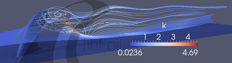


I hope this helps!
Hans
More pics from the same finFoil 1.1.1 data as the others:
-
3D printed fins, one printed flat the other printed stood up to counteract an ititial warping issue. Both are courtesy of a co-worker on a home machine.
-
Hand foiled FR4. Scrap 4 x .060" black from work with a layer of glass and white epoxy in between. I did not anticipate the black FR4 being purple on the inside. It’s only the 2nd FR4 one I’ve done by hand. My first attempt was with a bad choice of equipment (11k RPM angle grinder) a few years ago. This one was more fun with a variable speed sander with a choice of speed, pads, and grits. To get the picture to size I did a ‘alt+printscreen’ from finFoil and pasted it into Paint. From there the image can be resized or whatever is needed to get it to print 1:1.


Thanks Jrandy,
Do you notice any strength/stiffness difference between printing flat and upright?
You are welcome Hans. Your software makes this easier and more fun for me than regular CAD, thanks!
The one printed flat looks rougher on the foiled surface but more even when light shines through it. The back is fused together from being printed on the bed of the machine. It is less flexible which would seem to be stronger (more force to initiate a failure). There is more visual evidence of the printer alternating directions layer to layer, more of a plywood effect.
The one printed upright looks better on the surface but less even in transparency, especially in the trailing edge. It is easier to flex the middle of the fin. Since more of the lines printed leading to trailing edge it seems more like a grain effect and more likely to crack along a layer line.
Once I get a group picture I’d be open to more destructive testing.
Hey Hans. Thanks for making such a user friendly tool! I’ve been playing around with molding fins, and the potential to create new shapes for CNC is very exciting.
I am hoping for some help. I keep running into the same problem with the .stl files that finFoil generates. Basically, everything that gets generated is tiny (less than one cm in height). I have played with the dimensions on finfoil, have imported the .stl files to a number of CAD programs but I keep having the same issue. Looking at this form it is obviously that people are getting great results with finFoil, but I am obviously missing something. Has anyone else had this issue? Any possible solutions? Any help would be much appreciated.

Mstomres-
The finFoil STL output is in meters. Try adding a scale command to happen after the import.
1000 for mm, 100 for cm, 39.3701 for inches.
{
scale (1000)
import (“drive:/path/filename.stl”);
}
Simple fixes are the best! I aprceate the help. Now on to g-code.
seems like the one printed upright would be prone to breaking in half karate kick to board style, while the one printed flat would be less likely to break and in breaking it would seperate along one of the ‘foil steps’ delamination style.
what material are you using to print? ABS, nylon, Polycarbonate? i have been doing some things with an FDM machine that can use Ultem which has fairly strong flextural strength if printed in the correct orientation. would be interesting to try some fins with it…
another thing i have wanted to try is to cut out each layer of fabric to its net shape in the foil and layup your fin panel with with these staggered plies. you could resin infuse a dry fiber stackup or use prepreg. could get pretty close to your foil without a grinder. a CNC ply cutter and thin fabric could get you VERY close.
Hello G-
The orange ones are ABS on a low end hobby FDM machine. Using Ultem would be really nice. I have seem some airplane and of all things construction crane parts made from that. I would print the fins flat for strength too, maybe try to get the printing on a 45 degree bias instead of straight x/y to the world. My guy said that with a cleaner print bed and/or some tabs he could have gotten the flat one not to warp.
The stacking idea sound neat. You could even stick some other things in the stackup besides fiberglass or carbon fiber to reduce weight and gain thickness.
I’ve been playing with this program for a little now. I have to say the combination of a 3d printer, some carbon fiber a basic cad program to add tabs bases and or holes. I can build pretty much anything…
Wake board fins/kiteboard fins
surfboard fins
now working on a new set of wings for my hydrofoil. this’ll take a bit more cad work but This program and my printer does ALL the heavy lifting I just vac a layer or 2 f carbon on top
Still working on best way to have it pop out shiney without any real work
Dontation made.
If I find myself taking orders and using this program to design it I will donate a cut.
For now just playing with it and am super impressed.
Thank you for your work on this. Will post more pics as I build things that are pretty.
I have to make some modifications to the STL file. For the wing I am trying to make. I want to cut it in sections that are buildable on my printer, add holes and reassemble with some carbon rod to hold the pieces in place then carbon skin it.
Been using 123d design for any of the fins I’ve added bases too. It can add bits onto surfaces and add holes but surprisingly I can’t cut or section it.
There is a convert mesh to solid in 123d but this crashes anytime I try to use it. I know this isn’t a Cad forum but I figure a couple of you guys have crossed this bridge already and have used some good programs. Hans is defintitely an advanced foil modeler if he can make a program as easy to use as foil fin.
Any recommendations?
Or any recommendations for good programs for drawing foils that can take co-ordinate inputs. (that are free or available freely)
Never mind I found the following
http://u.tinkerine.com/en-ca/tutorials/3dmodeling/meshmixer/meshmixer-slicing.html