Hitachi Planer Mods w/ on the fly adjustment (I hope)

Hey everyone, been lurking for a long time and figured it was time to make a post. I recently picked up a new in box P20SB as a backup for my skil. Originally I was thinking, I would do the basic mods as it was going to be my back up. 

After countless hours of reading old threads I figured I was going to give it a shot and go for it all, handle relocation, new cord, bearings, vac attachment and on the fly depth adjustment. (I am also keeping a detailed list of all the parts used and where I got them, just in case it actually works!)

Here is a few pictures to get started! More parts are arriving daily, wish me luck!


Looks like an interesting and worthwhile project. I’ll be keen to see how it pans out. Wouldn’t mind giving this a go myself.


Video link for how to do the shoe:   https://www.youtube.com/watch?v=gPj78R5WqLo 


And how to do the handle:  https://www.youtube.com/watch?v=1fBHRpIcHBw

Thanks Mako. I am going to be doing the on the fly adjustment a little different. I found that the clutch cone and clutch driver from the Shimano 70 Type D coaster brake fit pretty much perfectly inside the front shoe and have a more agressive thread pattern, so it should be close to a 1/4 turn like on the Clark planer.

Below you can see that the clutch cone fits pretty much perfect in the front shoe. There is maybe a 1/16" of play in the two parts, I will epoxy the two parts together. The knurling on the outside of the clutch cone should help with the bonding. 

[[{“fid”:“106178”,“view_mode”:“default”,“fields”:{“format”:“default”,“alignment”:“”,“field_file_image_alt_text[und][0][value]”:false,“field_file_image_title_text[und][0][value]”:false},“type”:“media”,“field_deltas”:{“1”:{“format”:“default”,“alignment”:“”,“field_file_image_alt_text[und][0][value]”:false,“field_file_image_title_text[und][0][value]”:false}},“link_text”:null,“attributes”:{“class”:“media-element file-default”,“data-delta”:“1”}}]][[{“fid”:“106179”,“view_mode”:“default”,“fields”:{“format”:“default”,“alignment”:“”,“field_file_image_alt_text[und][0][value]”:false,“field_file_image_title_text[und][0][value]”:false},“type”:“media”,“field_deltas”:{“2”:{“format”:“default”,“alignment”:“”,“field_file_image_alt_text[und][0][value]”:false,“field_file_image_title_text[und][0][value]”:false}},“link_text”:null,“attributes”:{“class”:“media-element file-default”,“data-delta”:“2”}}]]

The clutch driver is a little long and too wide at the top to fit inside the front shoe guide on the planer body so that will have to be trimmed, all I really need are the threads anyway. There is a hole on the inside of the clutch driver, where the bike axle goes, that a 3/8" threaded rod fits into. The plan is to epoxy the threaded rod inside of the driver and that is what the new knob will connect to on the top of the planer. I hoping to just epoxy will hold but I am prepared to drill and set a pin if needed. 

[[{“fid”:“106181”,“view_mode”:“default”,“fields”:{“format”:“default”,“alignment”:“”,“field_file_image_alt_text[und][0][value]”:false,“field_file_image_title_text[und][0][value]”:false},“type”:“media”,“field_deltas”:{“3”:{“format”:“default”,“alignment”:“”,“field_file_image_alt_text[und][0][value]”:false,“field_file_image_title_text[und][0][value]”:false}},“link_text”:null,“attributes”:{“class”:“media-element file-default”,“data-delta”:“3”}}]]


This project, has all the earmarks of becoming a SWAYLOCK’S CLASSIC, and a valuable resource.      I hope other forum members will, as I have done, reward this effort with some LIKES.      I’m looking forward to the next steps.

It’s early days Bill, but I have high hopes. The force is strong with this one. 

Busy day today. I got almost as far as I can go until the front shoe adjustment knob comes in Thursday. I ordered he knob from Essentra Componets, formally Reid Supply, and it looks like it’s the same knob as on the Clark modified. 

I started the by filling in the hole left from drilling out the original post and the groove on the front shoe. I used JB Weld SteelStik, it reminded me of the epoxy ding repair sticks the Surftech used to sell. While that was curing I cut down the clutch driver down to fit in the front shoe guide. 

[[{“fid”:“106218”,“view_mode”:“default”,“fields”:{“format”:“default”,“alignment”:“”,“field_file_image_alt_text[und][0][value]”:false,“field_file_image_title_text[und][0][value]”:false},“type”:“media”,“field_deltas”:{“1”:{“format”:“default”,“alignment”:“”,“field_file_image_alt_text[und][0][value]”:false,“field_file_image_title_text[und][0][value]”:false}},“link_text”:null,“attributes”:{“class”:“media-element file-default”,“data-delta”:“1”}}]][[{“fid”:“106220”,“view_mode”:“default”,“fields”:{“format”:“default”,“alignment”:“”,“field_file_image_alt_text[und][0][value]”:false,“field_file_image_title_text[und][0][value]”:false},“type”:“media”,“field_deltas”:{“3”:{“format”:“default”,“alignment”:“”,“field_file_image_alt_text[und][0][value]”:false,“field_file_image_title_text[und][0][value]”:false}},“link_text”:null,“attributes”:{“class”:“media-element file-default”,“data-delta”:“3”}}]]

Next, I JB Welded the cut down cluth driver onto to a 3/8" threaded rod, which fit with about 1/16" of play, and the clutch cone into the front shoe. I did have a bit of a scare while setting the threaded rod into the clutch driver. I taped off the bottom hole to protect the threads from getting epoxy in them, but the thread is so coarse that as I pushed the rod in the epoxy seeped out and migrated up the threads. I spent a fair amount of time cleaning out the threads with acetone, but was able to get it clean. If I were to do it again, I probally wouldn’t tape off the end and just let the epoxy come out the end and sand it down after it cured.  

[[{“fid”:“106221”,“view_mode”:“default”,“fields”:{“format”:“default”,“alignment”:“”,“field_file_image_alt_text[und][0][value]”:false,“field_file_image_title_text[und][0][value]”:false},“type”:“media”,“field_deltas”:{“4”:{“format”:“default”,“alignment”:“”,“field_file_image_alt_text[und][0][value]”:false,“field_file_image_title_text[und][0][value]”:false}},“link_text”:null,“attributes”:{“class”:“media-element file-default”,“data-delta”:“4”}}]][[{“fid”:“106222”,“view_mode”:“default”,“fields”:{“format”:“default”,“alignment”:“”,“field_file_image_alt_text[und][0][value]”:false,“field_file_image_title_text[und][0][value]”:false},“type”:“media”,“field_deltas”:{“5”:{“format”:“default”,“alignment”:“”,“field_file_image_alt_text[und][0][value]”:false,“field_file_image_title_text[und][0][value]”:false}},“link_text”:null,“attributes”:{“class”:“media-element file-default”,“data-delta”:“5”}}]]

While these cured I got started on the handle relocation , new power cord and installation of the vaccum attachement. But that will come in another post. 

Thanks for posting this thread Mreuther, seems you’ve got people’s attention, including mine! 

When you say coaster brake hub, is this the brake mechanism for a foot-braking bicycle? By that, I mean the type of bike you backpedal to apply the brakes, as opposed to the hand-operated brakes? I’ve got an old planer I’d like to try this out on, but want to be clear on what I’m looking for.

Looking forward to further updates on your project.

Yes that is exactly what he is talking about.  You will find these parts inside of the hub of the rear wheel of pretty mych any of those bicycles.  Its pretty ingenous.  I’ve tinkered with bicycles my whole life and never thought to repurpose the guts of a hub.

looking great!

i think you will also need a collar and washer for the threaded rod (or top of your course thread depending on its length) where it comes out of the planer body

I have one on order, should be here Thursday also. I went with a threaded bore instead of a smooth bore, figuring that would give me more hold on the threaded rod. 

Continuing yesterday’s post…

While waiting for the epoxy to dry, I went ahead and did the handle relocation, added a 25’ cord and added the vac attachment. I’ll keep this post fairly short since this is pretty well documented on Sway’s on how to perform the handle relocation. 

The only thing I did different (I think) is that I used the the offcut from the dust sheild and made an insert for the bottom of handle so it would have more surface area to bond, I also added a screw just for good measure. This will also allow me to make any repairs to the wiring/trigger assembly if something were to go bad.

[[{“fid”:“106236”,“view_mode”:“default”,“fields”:{“format”:“default”,“alignment”:“”,“field_file_image_alt_text[und][0][value]”:false,“field_file_image_title_text[und][0][value]”:false},“type”:“media”,“field_deltas”:{“1”:{“format”:“default”,“alignment”:“”,“field_file_image_alt_text[und][0][value]”:false,“field_file_image_title_text[und][0][value]”:false}},“link_text”:null,“attributes”:{“class”:“media-element file-default”,“data-delta”:“1”}}]]

After setting the handle, I went ahead and sanded down the front shoe that was filled in with epoxy. I will round out edges of the front and rear shoe at a later time. 

[[{“fid”:“106237”,“view_mode”:“default”,“fields”:{“format”:“default”,“alignment”:“”,“field_file_image_alt_text[und][0][value]”:false,“field_file_image_title_text[und][0][value]”:false},“type”:“media”,“field_deltas”:{“2”:{“format”:“default”,“alignment”:“”,“field_file_image_alt_text[und][0][value]”:false,“field_file_image_title_text[und][0][value]”:false}},“link_text”:null,“attributes”:{“class”:“media-element file-default”,“data-delta”:“2”}}]]

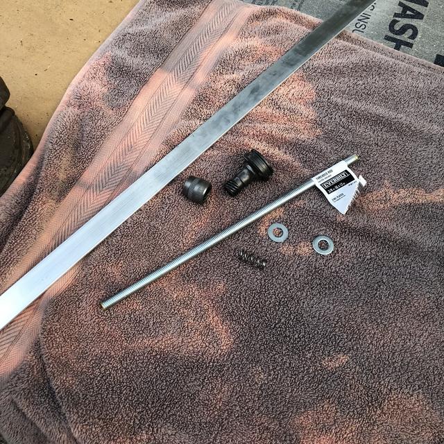
Now that the epoxy is cured on all of the depth adjustment parts I went ahead and test fit everything. It looks like its going to work, I just need to figure out what size spring will fit in the assembly, and I wont be able to figure that out until I get my knob and shaft collar on Thursday. I got a box of assorted springs from Home Depot, so I have a bunch to choose from. Here is what it looks like prior to going into the planer body.

[[{“fid”:“106238”,“view_mode”:“default”,“fields”:{“format”:“default”,“alignment”:“”,“field_file_image_alt_text[und][0][value]”:false,“field_file_image_title_text[und][0][value]”:false},“type”:“media”,“field_deltas”:{“3”:{“format”:“default”,“alignment”:“”,“field_file_image_alt_text[und][0][value]”:false,“field_file_image_title_text[und][0][value]”:false}},“link_text”:null,“attributes”:{“class”:“media-element file-default”,“data-delta”:“3”}}]]

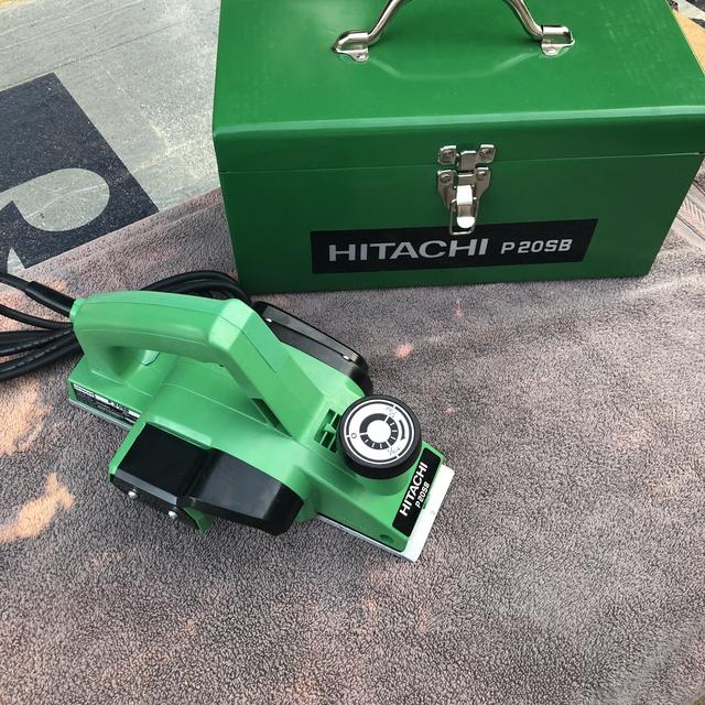
And here is where I am at until Thursday…

[[{“fid”:“106240”,“view_mode”:“default”,“fields”:{“format”:“default”,“alignment”:“”,“field_file_image_alt_text[und][0][value]”:false,“field_file_image_title_text[und][0][value]”:false},“type”:“media”,“field_deltas”:{“4”:{“format”:“default”,“alignment”:“”,“field_file_image_alt_text[und][0][value]”:false,“field_file_image_title_text[und][0][value]”:false}},“link_text”:null,“attributes”:{“class”:“media-element file-default”,“data-delta”:“4”}}]]


BONUS POST! 

So was sitting around the house today and it dawned on me that I could measure how much action I would get. I am using the bottom washer as my measuring point. I backed out the rod from the front shoe until it was at 1/2" and marked the rod. Then rotated the rod until it hit 3/8" and then look for the mark and see where my mark was. Low and behold I am right about at a quarter turn! For those wondering, turn the rod clockwise, and it compresses the entire assembly. 

[[{“fid”:“106241”,“view_mode”:“default”,“fields”:{“format”:“default”,“alignment”:“”,“field_file_image_alt_text[und][0][value]”:false,“field_file_image_title_text[und][0][value]”:false},“type”:“media”,“field_deltas”:{“1”:{“format”:“default”,“alignment”:“”,“field_file_image_alt_text[und][0][value]”:false,“field_file_image_title_text[und][0][value]”:false}},“link_text”:null,“attributes”:{“class”:“media-element file-default”,“data-delta”:“1”}}]][[{“fid”:“106242”,“view_mode”:“default”,“fields”:{“format”:“default”,“alignment”:“”,“field_file_image_alt_text[und][0][value]”:false,“field_file_image_title_text[und][0][value]”:false},“type”:“media”,“field_deltas”:{“2”:{“format”:“default”,“alignment”:“”,“field_file_image_alt_text[und][0][value]”:false,“field_file_image_title_text[und][0][value]”:false}},“link_text”:null,“attributes”:{“class”:“media-element file-default”,“data-delta”:“2”}}]][[{“fid”:“106243”,“view_mode”:“default”,“fields”:{“format”:“default”,“alignment”:“”,“field_file_image_alt_text[und][0][value]”:false,“field_file_image_title_text[und][0][value]”:false},“type”:“media”,“field_deltas”:{“3”:{“format”:“default”,“alignment”:“”,“field_file_image_alt_text[und][0][value]”:false,“field_file_image_title_text[und][0][value]”:false}},“link_text”:null,“attributes”:{“class”:“media-element file-default”,“data-delta”:“3”}}]]


The remaining parts from Essentra Components came in today, a threaded shaft collar and the front shoe adjustment knob. It’s all finally coming together and I can’t be more pleased. 

I first had to find what was zero cut, to do this I laid it on a flat surface then backed out the adjustment until the front shoe lifted the planer. I held everything in place and screwed on the shaft collar and tightened the set screw. 

[[{“fid”:“106308”,“view_mode”:“default”,“fields”:{“format”:“default”,“alignment”:“”,“field_file_image_alt_text[und][0][value]”:false,“field_file_image_title_text[und][0][value]”:false},“type”:“media”,“field_deltas”:{“1”:{“format”:“default”,“alignment”:“”,“field_file_image_alt_text[und][0][value]”:false,“field_file_image_title_text[und][0][value]”:false}},“link_text”:null,“attributes”:{“class”:“media-element file-default”,“data-delta”:“1”}}]]

Then I measured the depth of the thread that the knob would take and trimmed the threaded rod. Screwed the knob on and it looks like we are good to go…so I thought. 

What I didn’t take into consideration was what stops the front shoe from backing all of the way out. I need to figure out a way to make a stop so that the knob cant turn past zero, open to suggestions on this one.

[[{“fid”:“106309”,“view_mode”:“default”,“fields”:{“format”:“default”,“alignment”:“”,“field_file_image_alt_text[und][0][value]”:false,“field_file_image_title_text[und][0][value]”:false},“type”:“media”,“field_deltas”:{“2”:{“format”:“default”,“alignment”:“”,“field_file_image_alt_text[und][0][value]”:false,“field_file_image_title_text[und][0][value]”:false}},“link_text”:null,“attributes”:{“class”:“media-element file-default”,“data-delta”:“2”}}]]


Drill and dap a second hole in your collar to accept a long hex head screw.  The long screw is against the body of the planer when you are at Zero.

I have two ideas on a stop: 

1 - Use the existing threaded brass fitting on the side of the front shoe housing, drill all the way through the body until it hits the cylinder on the front shoe, tap the hole, create a slot on the front shoe cylinder and then screw a machine screw in so that it fits just inside the slot that was created in the shoe. This would act as a pin stopping the shoe from being backed out further than zero. 

2 - Get a longer screw for the shaft collar and add a pin to the planer body under the knob that would stop rotation of the knob past zero 

I think that will be the easiest route

[[{“fid”:“106312”,“view_mode”:“default”,“fields”:{“format”:“default”,“alignment”:“”,“field_file_image_alt_text[und][0][value]”:false,“field_file_image_title_text[und][0][value]”:false},“type”:“media”,“field_deltas”:{“1”:{“format”:“default”,“alignment”:“”,“field_file_image_alt_text[und][0][value]”:false,“field_file_image_title_text[und][0][value]”:false}},“link_text”:null,“attributes”:{“class”:“media-element file-default”,“data-delta”:“1”}}]]


Here is a picture of my Hitachi planer and you can see how I’ve drilled and tapped a second hole that accepts a hex head screw that is concealed inside those white spacers.  When I am zeroed out the knob is turned so that the white piece is pinned against the body then I tighten the set screw.

loving this

all the best