hi dave
Your avatar looks good, might surf ok … maybe not, I like the fin.
hi dave
Your avatar looks good, might surf ok … maybe not, I like the fin.
Nice graphics and geometry-based design technology. The use of geometry can create some very clean outline/template curves. It should be very easy for CAD adepts to use.
Thanks for posting.
EDIT: How are you generating the curve (rocker curve) that transects the cylinder to create the template outline? Seems like a geometric or some other math generated curve could create something that could be replicated quickly/precisely with a very clean rocker curve/line.
Hi Malaroo,
I’ve been playing with OpenSCAD for 30 minutes, by doing so I cleared out some questions I had.
I’m not ready to post pictures tough, but I believe that you’ll like the parametrization possibilities of OpenSCAD. Hopefully I’ll post the first pictures tomorrow.
I still have one question about your pictures: The cut in pic 2, is that used to create the rocker line? So this means that you’re using an elliptic rocker line?
I started by creating an elliptic rocker line, by cutting and scaling a circle. I’m writing it in a way so that you can switch rocker profiles easily.
Good fun!
Hans
I recently created a template using PowerPoint (PPt), ellipses, midpoints and straight lines. Math-based design but with nothing more than the desired SB dimensions and the ability to create ellipses and straight lines with PPt. Allows me to design clean template curves while being CAD illiterate. Convert to a JPEG or PNG file, find a banner printer and you have a template.
I will post some of my PPt graphics later. No time to convert files at the moment.
Still looking for some simple math to create rocker curves. This is why I asked about your method for rocker curve design.
Thanks Malaroo,
Those pics have deinitely helped me to understand more about your proceedure.
I took solidworks last semester at our local college. They don’t offer any advanced classes in that subject so I’m having to try to learn what I can on my own (through You Tube University) there’s a lot of info out there but it can get pretty frustrating when things don’t go quite as expected.
I’m taking autocad inventor this semester just to expand my knowledge base but I’m really just going over the same stuff I did last term and not learning much new there.
I will spend some more time trying to get a better grip on your process and fiddle around with the concept in the program.
Whatever else you could post to explain your process in more detail would be greatly appreciated.
hi Hans
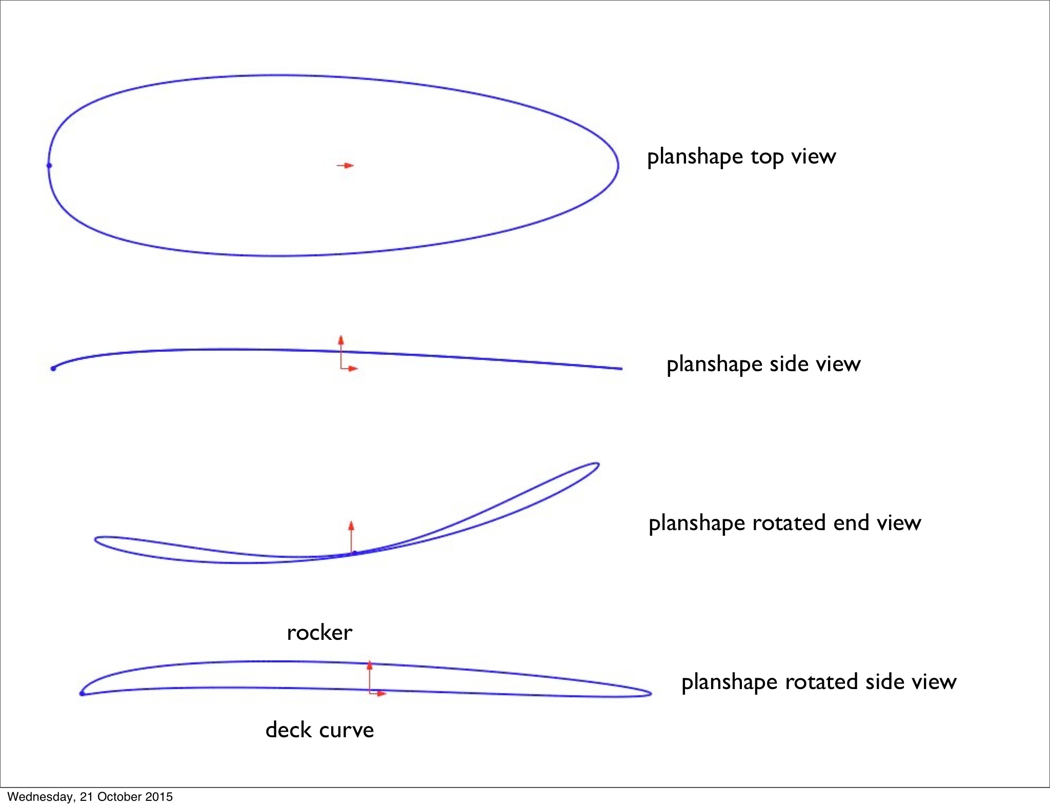
A quick answer to your question about rocker is that the ellipse is then put through the cylinder again as a plane and that creates a mal plan shape at the point of intersection with the circle. That mal plan shape is then rotated around the nose to tail axis, but viewed from the side, this raises one side edge and lowers the other side edge, and that projected onto a centre plane (as you see it anyway from the side) gives you the rocker and the deck curve (design relativity). It is like an ellipse that is bent up at the nose and tail.
I used to make templates for hand shapers 1982/83 and when I analysed the rocker curves, I could put a corresponding ellipse over them but the nose and tail were bent up. I was so thrilled when I discovered this method uses the classic planshape to create the rocker and that lifts the ends. There are many rocker otions, I found the one I am showing you is a classic and can be mixed with any plan shape and it will work. Some plan shapes create rockers that don’t work. I found that out the expensive way. Soon we will get openSCAD going and it will become clear.
I’ve had a busy night and have only had 2 hours sleep since yesterday, I’m off to bed to awaken and get on with things. Thanks Hans and everyone that has replied … I really apppreciate your interest.
hi Stoneburner
I think you need a 3dCAD to get the rocker, hopefully we can get openSCAD going and that option will fullfill your rocker quest (in 2D image of the 3D curve viewed side on). Also the difference between engineering CADs like Solidworks and PPt is you can do everything to exact measurements … Am I wrong, isn’t power point a drag and draw option only? Or can you select ellipse and give it a length and width and it will appear?
hi Stoneburner
There is a bit of acrobatics involved in getting the ellipse to create the outline, I’ll post detailed steps later today (I hope), the acrobatic bit is that the ellipse created from the angled slice is longer than the boards length, however the front curved end of the ellipse is too curved to use for an outline, so I cut the front off by using an arc the radius of the boards length centred at the tail end of the ellipse. The other acrobatic bit is getting that cut ellipse into position so that each end is on the outside of the cylinder. The cut ellipse is then turned into a slice through the cylinder to get the intersection curves. Does that make sense?
moved to last post so it will not get buried in older posts…
I think I understand how you are creating the non-elliptical shape – your cylinder transect line/plane is curved rather than straight (?). I am still a little vague about how you are creating the shape of that transect curve. The transect curve is the rocker curve. Am I interpreting this correctly?
You can determine length and width of your ellipses down to hundredths of a inch with PPt. The drag and draw feature is handy where it would take much too much calculation to get the precise transect curve of the ellipse needed to create the tail. While I cannot print a full-size template through PPt, I can save the image I have created as a picture in several formats. The saved image will have the exact dimensions that you created it to have and can be printed with a banner printer.
I use 2 separate ellipses (different sizes) one for the nose and one for the tail. Ellipse sizes are determined by the location of the widest point, total board length and desired tail curve profile. When you join the 2 ellipses at their midlines, they create a perfectly blended curve (no joining seams). The range of shapes that can be created with the double ellipse method is broad.
It would be nice if I could come up with some simple math to generate a rocker curve though.
hi Stoneburner
I have designed boards with the double ellipse method, they are a bit different to the ones done with the 3d method, whether that difference matters in sufing is questionable. They probably work fine. As for the rocker by using the method I do the rocker is in most cases the planshape but scaled down about a quarter so + or - depending on choice. So you get your double ellipse planshape and as you say PPt will give you exact measurements, Ok, I am learning as I type, but I think I have your solution. this is different to what I do, so I am just considering an option. I will do a drawing for you if you ask me to, but I’ll first try and explain in words now. You know how your ellipse has a length and a width, so if you go to the flattened end of the ellipse at the width corner, then draw a circle the length of the ellipse but from the widest point corner and cut the ellipse at the curved end where your circle intersects it, then you have a trimmed the curved tip off the ellipse, do that to the both of them, together they should be the length of your board … OMG I hope I am right and they are … then scale your cut ellipses to about a quarter of the width they are … is that possible with a cut off ellipse in PPt? I have no idea, if so your laughing, got your rocker. With 3D cad if you tilt a circle and project the outline you get an oval … so we are trying to achieve the same effect by scaling the width down. Does that make sense to you? It might be bullshit because the lengths are on an angle and it might be too short … ??? Let me know if that helps or just spun you into a pile of bullshit.
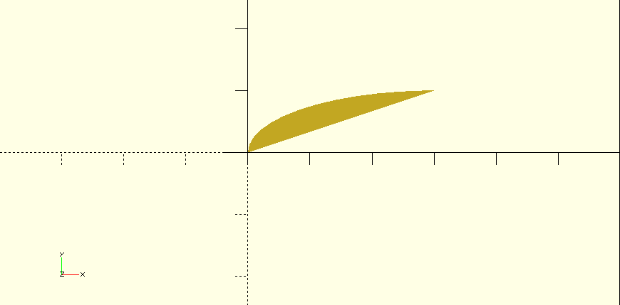
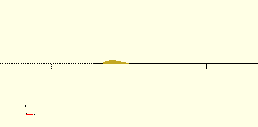
Here is my first OpenSCAD attemt to get somewhere. Hopefully, I’m working in the right direction and it could clear up some questions people have.
Find the OpenSCAD files here: https://gist.github.com/hrobeers/c0280ccdc7930e414ee7 (should be placed in same folder)
I’ll walk through the pics reading the files from bottom to top, references to pictures are added in files!
pic 1: base circle

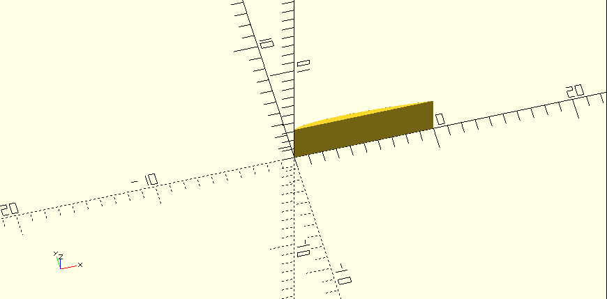
pic 2: cut circle at 45deg

pic 3: scale to ellipse
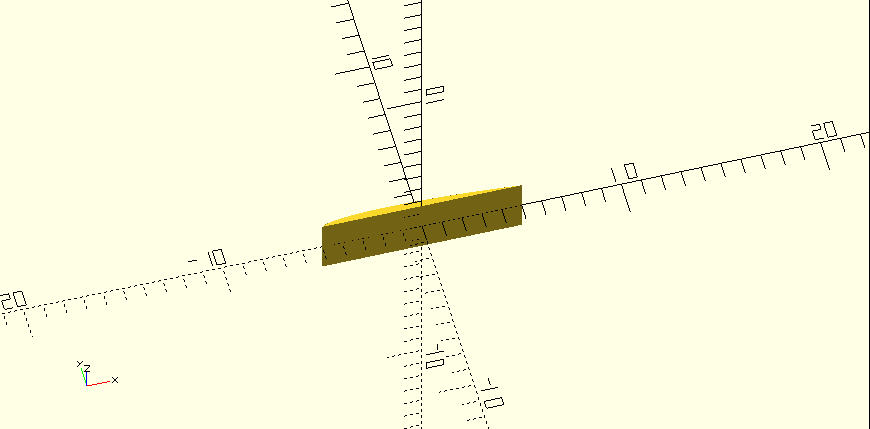
pic 4: rotate to x-axis
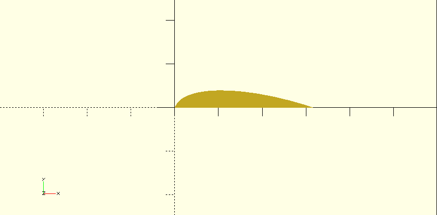
pic 5: normalize to length 1
pic 6: scale to length

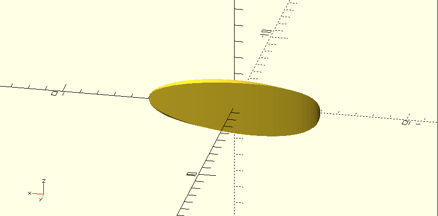
pic 7: extrude to thickness
pic 8: center
pic 9: cylinder

pic 10: rotate cylinder in place
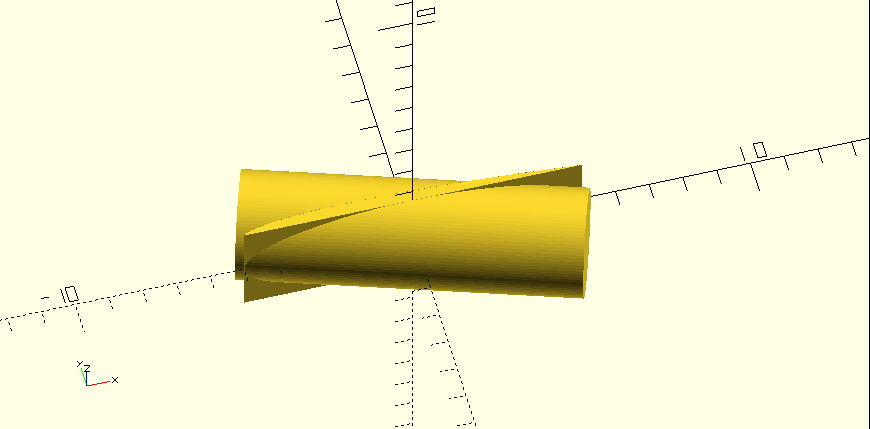
pic 11: intersect

pic 12: other viewing angle
Now I still need to understand how the deck rocker and rails are created, and get the right parameters exposed.
I am pretty sure I know how Malaroo get his non-elliptical template shape. I am still a bit confused about designing the rocker curve. Yes I can scale any image created by or inported into PPt. I can tweek things a bit with Photoshop too.
I have a busy few days. I have stayed up way too late already. But I will try to post some 2-D graphics of my grasp of the cylinder transect.
My 2-D double ellipse method may be slightly different than yours Malaroo but very similar.
I need to get some sleep now…
Ok … after reading this thread I’m completely bamboosled and with all due respect I fail to understand how this design method will change anything. I am cogniscent that surfboard and fin design relates most definately with the arc of the circle concept but how can this improve upon the AKU shaper regime already in place whereby with some ten or so peramiters a blank is shaped. Are you saying you have discovered a subtle tweak refinement? If so, I like it.
PS. I’m a nuts and bolts sort of a guy and all the computer programs bewilder me …sooo in laymans terms what’s this all about? ;)
Hi Quanta,
How I see it, Malaroo found a way to define his magic formula for different board sizes.
It’s not a general truth, it just works for him!
Some may find it an interesting path to learn more about, while others just don’t like it.
I’d like to compare it with Piet Modriaan. Some love him, others don’t like his work. But what he does is similar, he takes a complex shape and simplifies it by abstraction.

Some people like it, others don’t. It’s art.
For fun, get a pencil, a flexible wood strip, and design a board that way… Immensely satisfying in a way a CAD design never can… That is if you want to be considered a craftsman… You will see things differently…
This stuff goes over my head, but kudos to malaroo for posting up and sharing, that’s what this forum is all about. Always amazes me how much some people put into this forum, for free, and asking nothing back.
Math is the language of creation and the underpinning of the physical universe.
This thread lasted to page 4.
At least it has provided a classic example to illustrate my ongoing discussion with Mike Paler.
Hi hans
Well that’s impressive, there are a few things that are different to mine, but that might not matter, the main thing I see that has to change is the elliptical shape through the cylinder, it has to be just an elliptical surface, like a plane, the thickness created to the line joining each end is in the way of getting the rocker and deck curve … it has to go. Can you easily change that? You will then see as the outline is rotated and viewed from the side, the rocker and deck curve will show, if you view it as lines not a rendered surface.
Malaroo,
So from my perspective (if correct), your “planshape sideview” is the curved plane that transects the cylinder…
Still having trouble seeing how the curve is created. Not that important for you to try and explain it to me though.