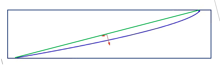
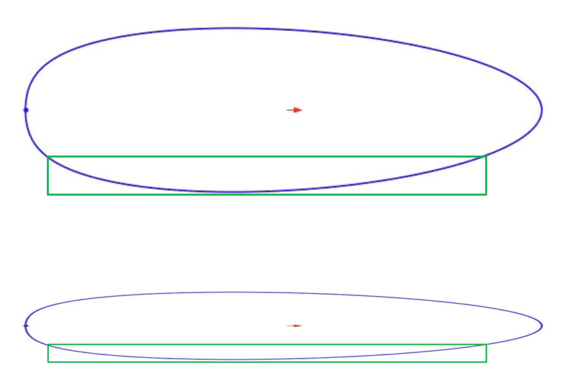
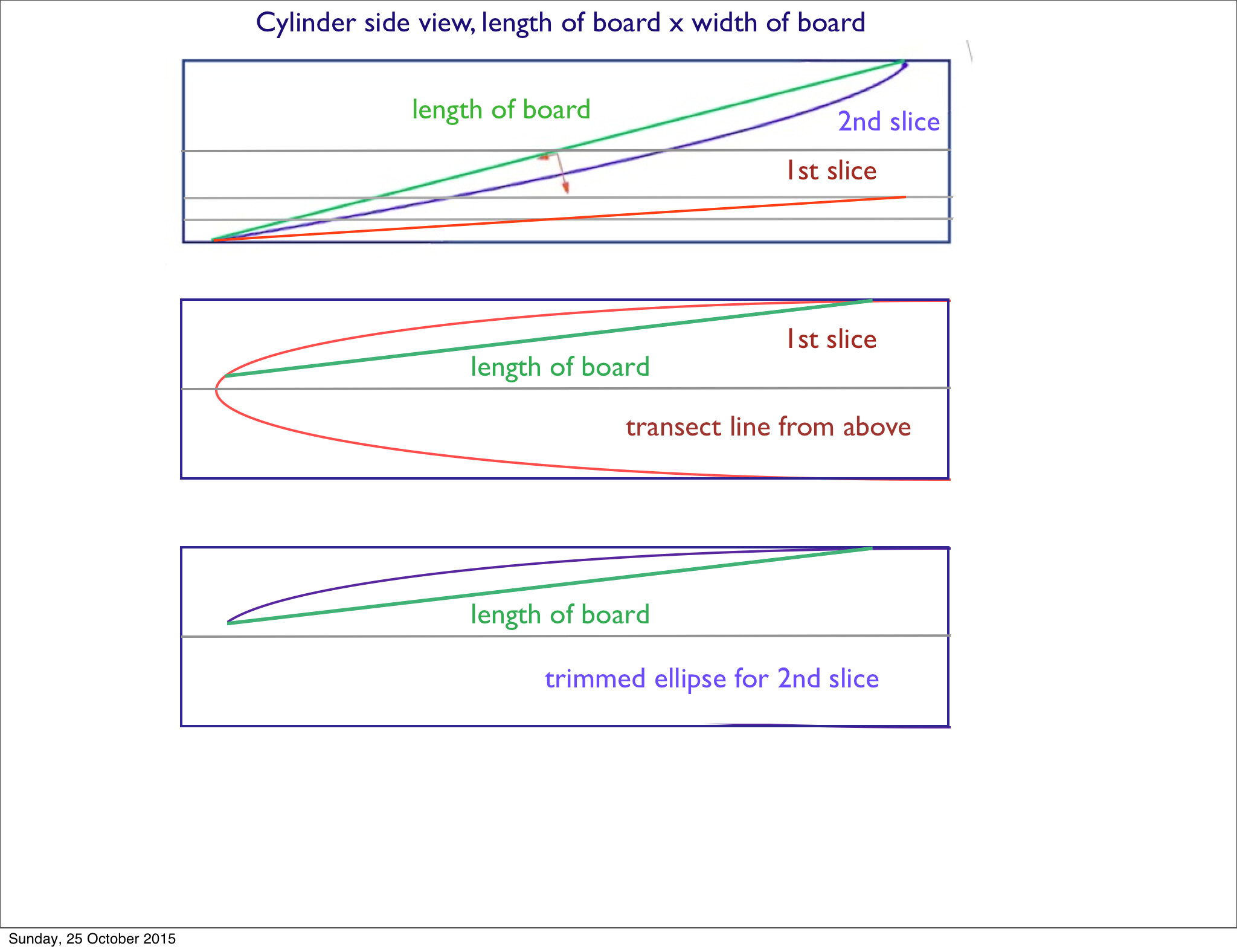
This is my 2-D graphic interpretation of what you do Malaroo.
The cylinder sideview is the black rectangle. The flat plane (green) cylinder transect would create an elliptical planshape. The curved plane (blue) cylinder transect creates your non-elliptical planshape.
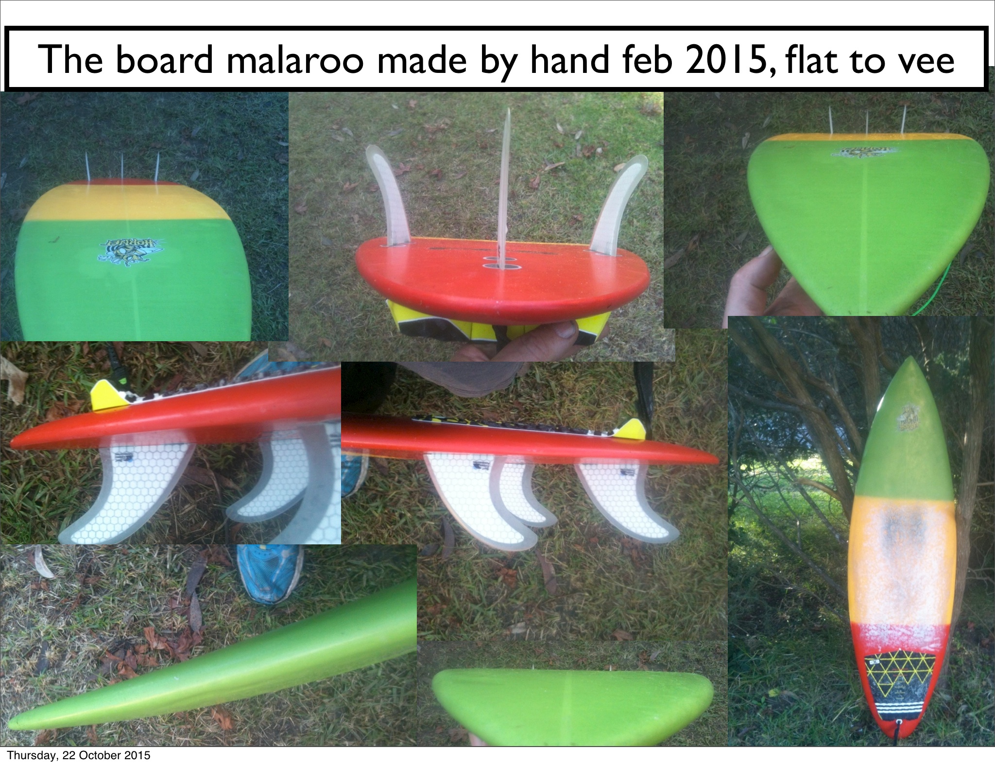
Earlier this year I made a board by hand for friends 13 year old kid, sighted it by eye only, used long sticks with sand paper taped on the end, took me three days to get the bottom and the rails right blending all the curves, flat to vee. The kid loves it and is surfing every chance he can, which is a lot. His father tells me on the week ends he leaves in the morning surfs all day comes home in his wetsuit at dinner time. I’m making one for his dad and myself now … by hand, we have another two people that want one. I like making mine by hand because I can control every aspect of it, and as you say it’s fun. for me its not profitable, I take a long time to get it right. My geometry boards are fun to ride, they do work and the system can be used to make any board if you know how to use it. I sold 207 of them, while I was developing this stuff, (before I became a victim of a dodgy mortgage company and lost everything, litigation is still ongoing) guys won competitions on them, people ask for them all the time, every week someone asks for one. I haven’t been able to make them since 2008. Great business tool because you can replicate a model easily and knock them out fast and accurately.
That’s right, it doesn’t work for all boards, so for example a reverse plan shape line a McCoy, the rocker is actually reversed to the plan shape. The rocker is scaled down by the same principal as looking at a circle and tilting it to become an oval. that way the rocker is related to the boards planshape, (design relativity) I think your brain can see it when you hand shape anyway.
I have only a few cents of internet credit left, looks like I’m going on an offline holiday for a while, it could be a week … Bugger, Will see if I can sort it out soon.
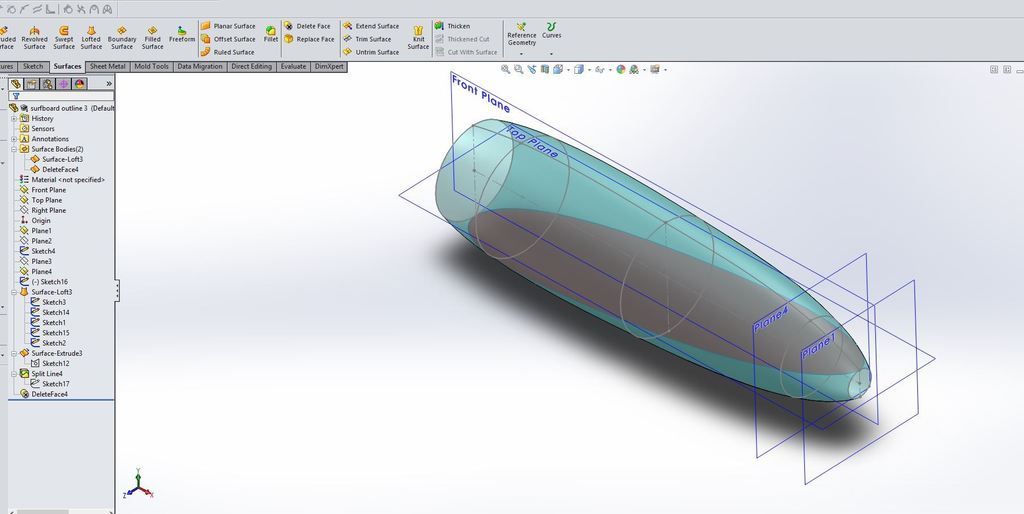
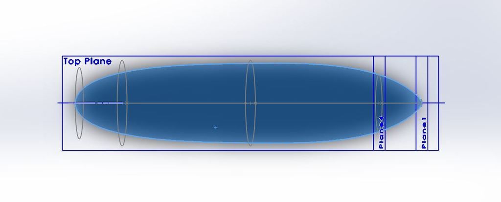
I’ve played around with the idea a little bit today, I’m still trying to wrap my head around how to create rocker this way but the cylinder works great for outlines.
by using a lofted surface and changing the diameter of the cylinder at different points. I was able to gain a little more control over the contour.
manipulating the guide curves could also increase the amount of control.
These are still just surfaces at this point but even this could produce a decent template.
thanks malaroo! I was in over my head until hans stepped up with that great OpenScad series of pictures (thanks hans!) I’ll be following this with interest. Like Huck said, passing on new ideas, thoughts, methods, (whether it’s your cup of tea or not) is what makes this site so worthwhile. Keep it coming, all!
Here’s an old thread where malaroo posted a bunch of pictures and lots of details. Really interesting stuff and this link starts at page 8 and the thread is 28 pages long, so grab a cold beverage and dig in -
Good to see you back on here malaroo. I had actually thought about your board designs a few weeks ago. I met a guy locally who has an APS3000 machine and does contract glassing as well. Might hit you up for a finished file to cut and try out at some point.
thanks for the acknowledgment biggreen, sometimes wonder if anyone reads half the stuff I write, lol. I would like to think I might bear a little guilt for this mind-numbing madness (in spite of it being way over my pay grade), as I had been in contact with Malaroo for some time, via PM, encouraging him to get back on here and share his unique math genius. The site needs more guys like him, stoked and willing to share, teach, and explain. I think a site glitch was keeping him away, but like lawless mentioned above, I too am glad to see his return.
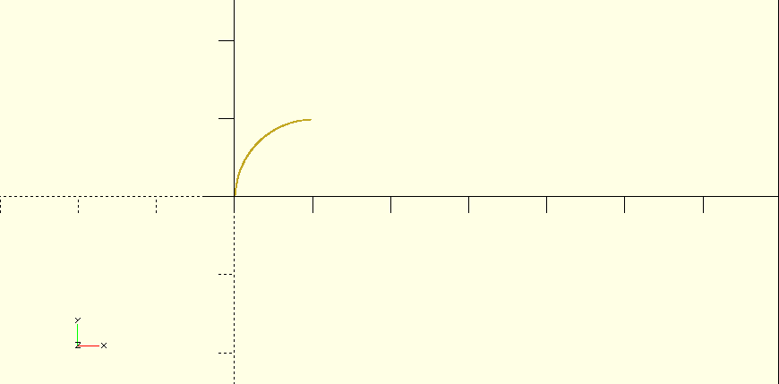
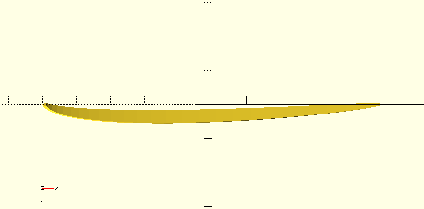
3: Cut by circle translated a little bit to become a thin arc
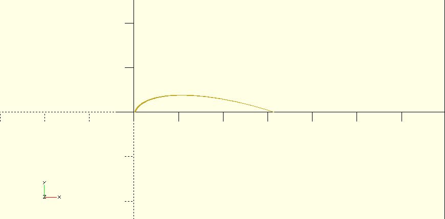
4: Transform like in previous series
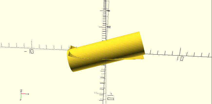
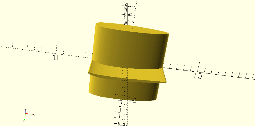
5: Cut the cylinder
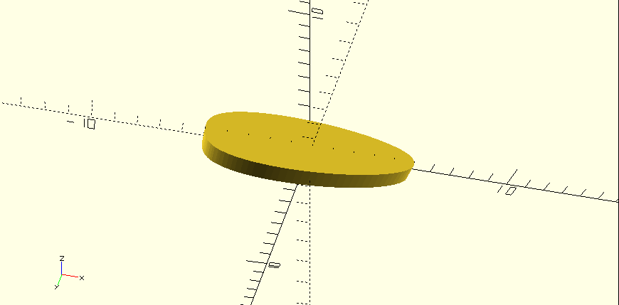
6: Project & extrude for the outline
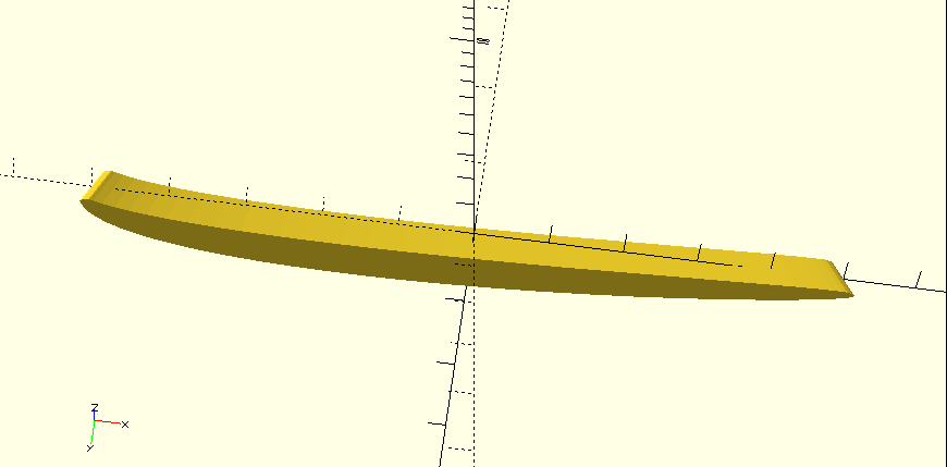
7: Rotate the thin cut from step 5 by 7 degrees around the x-axis. Look how the top & bottom rocker appear! This is just the thin surface rotated!
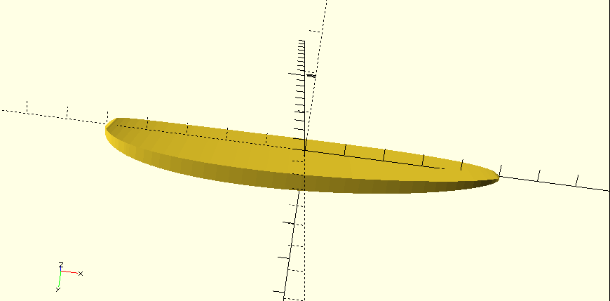
8: Project & extrude
9: Combine the extruded outline & rocker
10: Intersect
We now have a Malaroo blank!
@Malaroo, what’s the procedure for the rails & deck dome?
How cool is it that multiple people are doing the same stuff in different CAD applications, but still learning from each other because it’s all about the math and not about the tool?
Interesting Hans. But I still do not see where the circle comes from. Then how are you converting the symmetrical curve created from the circle into an assymetric curve. Are you just stretching the arc in your graphic from its right side beginning at its (symmetrical curve’s) midpoint?
This method places the board’s widepoint at the rocker curve “apex.”
When both you and Malaroo mentioned spinning a planshape from topview towards side view to create gentler curves, something occured to me. You could do this same spin distortion to create a bottom rocker curve from any board’s planshape. However again, this places rocker apex at the wide point of the board.
I have been playing around with this in 2-D. I can see a starting point for a fairly simple method to create planshape-based bottom rocker, by unlocking the planshape aspect ratio and compressing width (below). Still need to come up with something simple for deck rocker.
Wow!! Good on you, Huck, for putting in the effort to help bring malaroo back! You might well be The Golden Peach!
Having a father who was a physicist and Mission Control scientist during all the moon flights, but receiving the short straw when it came to understanding things mathematical, having someone open your eyes with understanding is cool. Thanks to malaroo, hans, and stoneburner. This is great stuff!
You can loft a rocker curve with 2 nails, a loop of string, and a pencil. The nails set far apart from each other and the string, are used to draw an elipse, then select a portion of the elipse that is the rocker you are after. Use the computer between your ears. Lots of ways to get there. Me, I just hand draw the rocker curve, then use board templates as ‘‘French Curves’’ to clean things up.
Mr. Thrailkill, I just tried your method. maybe I didn’t quite understand correctly.
I did learn however that LCD’s don’t respond well to nails being driven into them.
oh well it was about time for a new monitor anyway. lol
I hope you don’t take the rest of this as negativity but I’ve been building things with my hands and the “computer between my ears” for most of my life, I’ve built all kinds of things large and small sometimes without so much as a tape measure ( using what’s known as a story stick),
I understand the appeal of relying completely on one’s wit and imagination to build something.
I also understand that there are usually many ways to accomplish any given task, each method has it’s benefits and drawbacks.
learning to draw surfboard shapes on a computer is not an affront to craftsmanship. It is merely a different method of achieving a result.
One that can be practiced quietly in the comfort of my home at any time of day or night I feel compelled to do so without commiting a single cent for materials or disturbing my family.
I as well as others here find enjoyment in learning new things as much as building new things. Learning how to use a computer in this way is just another one of those things.
I appreciate your experience and considerable contribution to this site as well as Mr. Jensen’s and thank you both for your input.
That is most likely true. The operative comment I made, that you seem to have missed, was that ‘‘there are lots of ways to get there.’’ I just pointed out a non electronic, low tech way, to accomplish a fairly sophisticated result. You went the long way around the barn, to point out the same thing. So, we’re in agreement, there ARE lots of ways to get there.
Thanks Bill for bringing up that method for drawing an ellipse.
That is a good way to transfer the virtual model to reality.
Speaking as a backyard builder without CNC machines, these computer models help us create our mental model of the board. An experienced shaper’s mental model is way more detailed than that of a backyarder. Computer tools help here for the less experienced hand shapers.
finFoil is also designed for hand builders. The contours are meant to help the handfoiler foil the profile that he has in mind. There are 3D export possibilities now, but these are not open source.
@ Bill, do you have an idea how we can achieve the projection of the rotated outline for the deck & bottom rocker combination?
The main difference between my method and AKU, is that you can’t create my boards on AKU without creating them first on another 3D engineering CAD. My designs start from slicing a cylinder (that can be a variety of different types of odd cylinders, circles to ovals, circles to squares etc and all sorts of slices.) and from the result of that comes a plan shape, from the plan shape comes the rocker and deck stringer lines, from them is the rail point of change line on the planshape, from there is the bottom (of your choice) concave, flat to vee, rolled vee, double concave, super deep concave. From there the deck type, (your choice) I prefer elliptical, from there the bottom rail sections. Then … the fins can be automatically designed and placed from the boards dimensions and using certain fin placement rules. (helps you buy fins that are close to what a formula says will suite). You can design my boards by using a quarter as a guide to making decisions. centreline to widest point, divided by 4 = thickness, short board shape, width x 4 = length.
Also AKU can’t read engineering files like iges files and DXF files. Very frustrating, I have had many email discussions with Jimi from AKU. My ambition is to develop a CAD like AKU where you can select the planshape and then just play with the variables, and the board is automatically designed, with the fins. I have no doubt that I am self deluded about the potential of my system, but that’s me and I have to do what I do.