Do I need to start a new thread to disscuss these theories - Rail shape , fin size and placement etc. ?
hi Wooddave
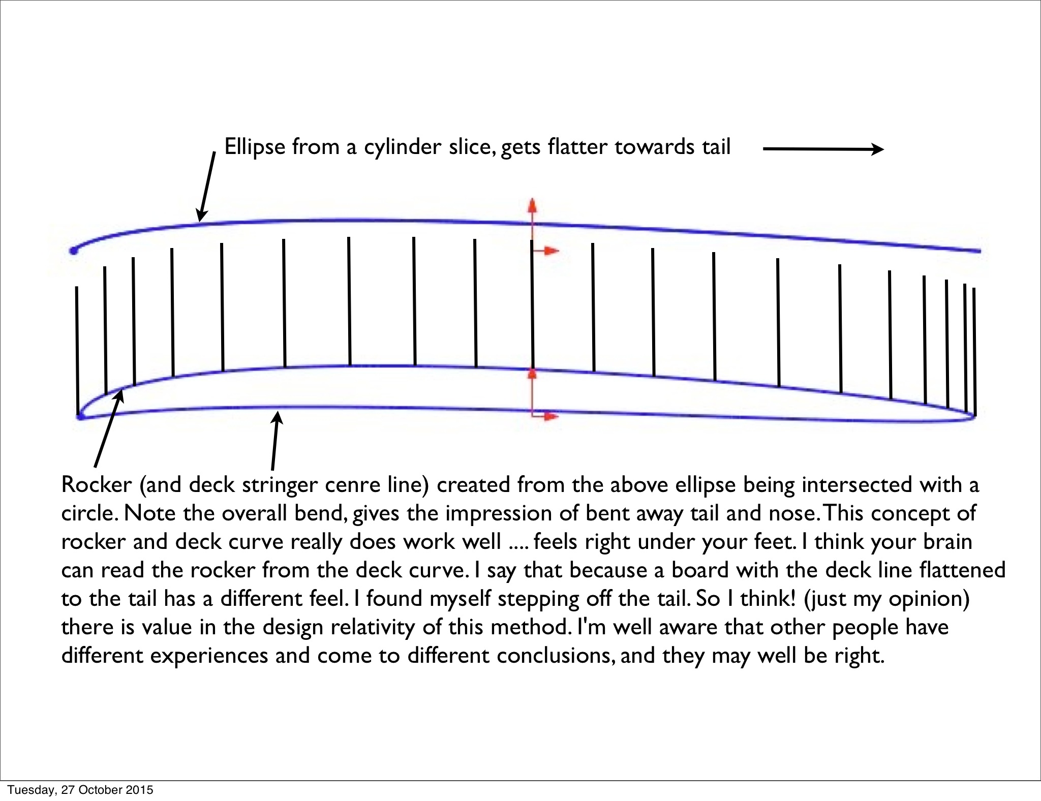
Here is a quick pic to show the comparison of the ellipse created from a sliced cylider to the rocker created from the ellipse by intersecting the ellipse with the cylinder (my second attempt to post this, will it double post … that is the question?)
Hi Greggriffin
I’m sure your request represents the curiousity of many. I will try and put together something for you today. A quick overview for now to show you the ideas are real.
Yes please.
I would very much like to see how Malaroo designs his rail profiles.
Maybe you would be willing to show us how you design rail profiles also Mr. G. What geometry do you use to create them?
At one point there were 2 top shapers
One had flowing oval like curves in every aspect
The other used “Parts” combined to create each aspect
The shaper using “Parts” became the # 1 designer in the world because these boards had unlimited speed , control and freedom .
Staged Rocker is a term some use and refers to using a combination of sections and angles - “parts” to create the overall rocker of the board .
Al Merrick did this .
hi stoneburner and Greggriffin
Its really very simple and you stoneburner of all people already know it. (the elephant in the room … so obvious) I’ve sent a letter to Santa requesting a 3D CAD to you for christmas. I hope Santa is real and you do get one. The ellipse that creates the planshape, (planshape bent to an ellpise) mixed with the rotated planshape that gives the rocker and deck stringer curves combined gives the planshape rail changing points. (deck above, rail below) With 3D CAD (brain explosion) its then easy to use your rail and deck profiles from your blog at 90 degrees to the centre line to create the deck, then fillet your radiui (connect the rail line planshape by radius) to the bottoms outer edge. That’s it … so simple. If you had a 3D CAD now it would be done in half an hour … nudge nudge!
By the way anyone can get a free student version of Solidworks, (one of the worlds biggest CAD systems) go to solidworks site for info. It’s free for a few years. Full of tutorials. and you can become accredited by doing tests online.
hi Greggriffin
Have you got any mor einfo on staged rocker? Does Al merrick use a resin edge at the tail end? They can so seasily be done badly and ruin a board, but ofcourse they can be done well and work nicely.
Malaroo, my question about rails is/was sincere. I am always interested how others do rails. Never know when I might pick up a genuine pearl to add to my cache.
Yes CAD would make all of this very easy. But it has been fun learning how to get a common 2-D graphics program to do what I want. I will have to check out SolidWorks when things settle down for me.
Hi stoneburner
I knew you were sincere and I sincerely meant that your blog has the answers, I wasn’t being sarcastic. If I said to you I do it this way, (which is your way) it would have been an insult because, it is in your blog. As I understand it, you have covered the concept the only way it can be done geometrically. What you do with 2d CAD is pretty amazing, I think you would really enjoy 3D CAD as well. Sorry if you thought I was sending you up, I meant it with full respect of your achievements. I was sending up the limitations of 2D CAD (not you) because if you had a 3D cad you could have done a whole board with your concepts.
No worries. I understood.
I have been wanting to learn 3-D CAD for years now. No opportunities available nearby. Having only 2 dimensions to use has pushed my PPt graphics beyond what I thought was possible. Before PPt and Photoshop, I would have had to do this with math, graph paper, a calculator, ruler, protractor, compass, a few other drawing tools and or/freehand.
I would not have discovered a planshape based rocker concept if I had not participated in your thread. This thread is why I come to Sways.
Onward Thru the Fog
Hi stoneburner
Were going to have a lot of fun! I’ve been working on a detailed step by step in Solidworks, will have that for everyone soon. Hope to do that in openSCAD with Hans as well. Wooddave has done another great post that just appeared back a few pages, worth a look if anyone missed it.
… the fog is always followed by a bright sunny day.
You are right. WoodDave has taken his SolidWorks skills to the next level. This is why I dislike using the reply feature – buries new posts deep in the thread where they go unnoticed. Here is the link to the WoodDave post Malaroo just mentioned:
Malaroo Surfboard Geometry: designed/invented by malaroo 2004
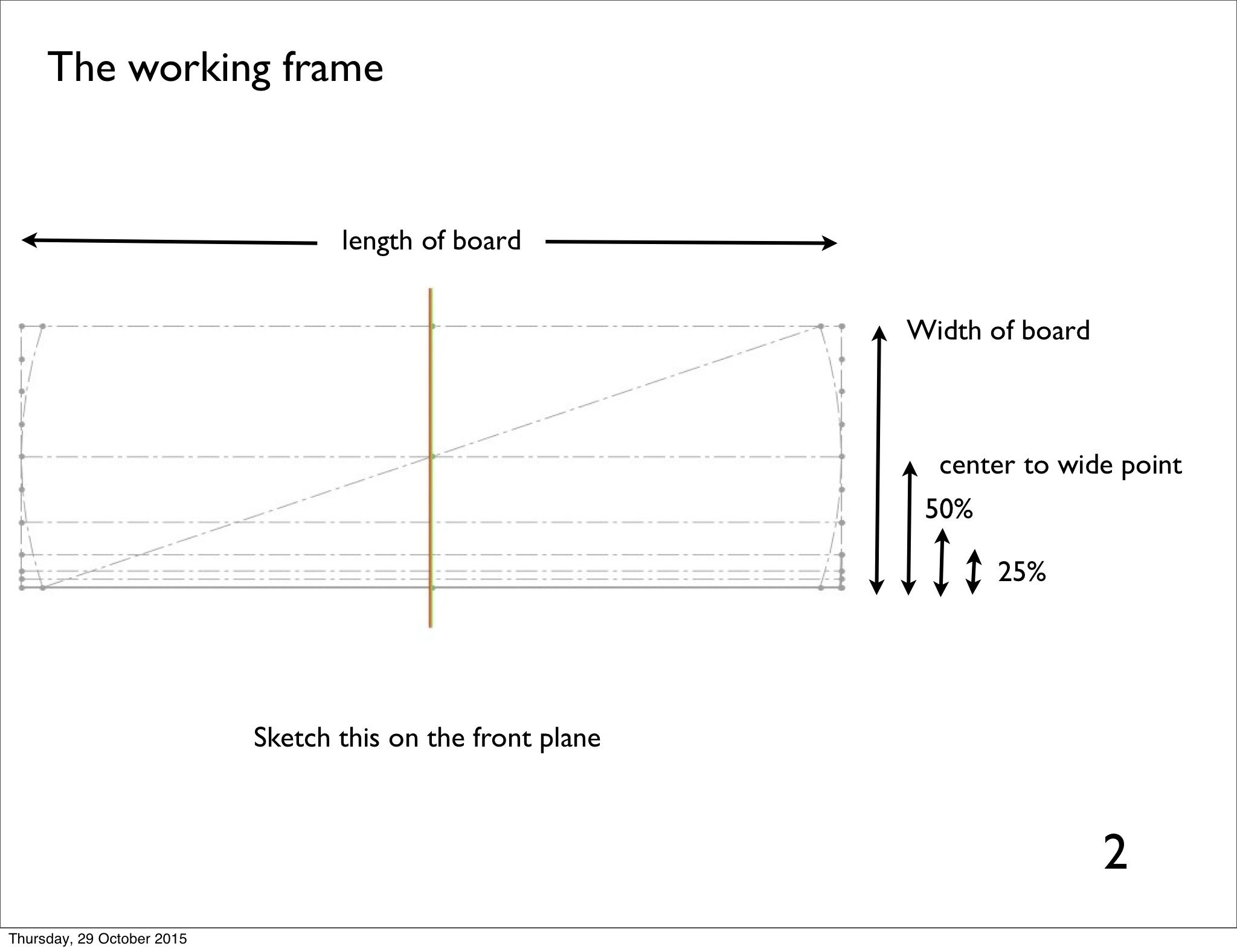
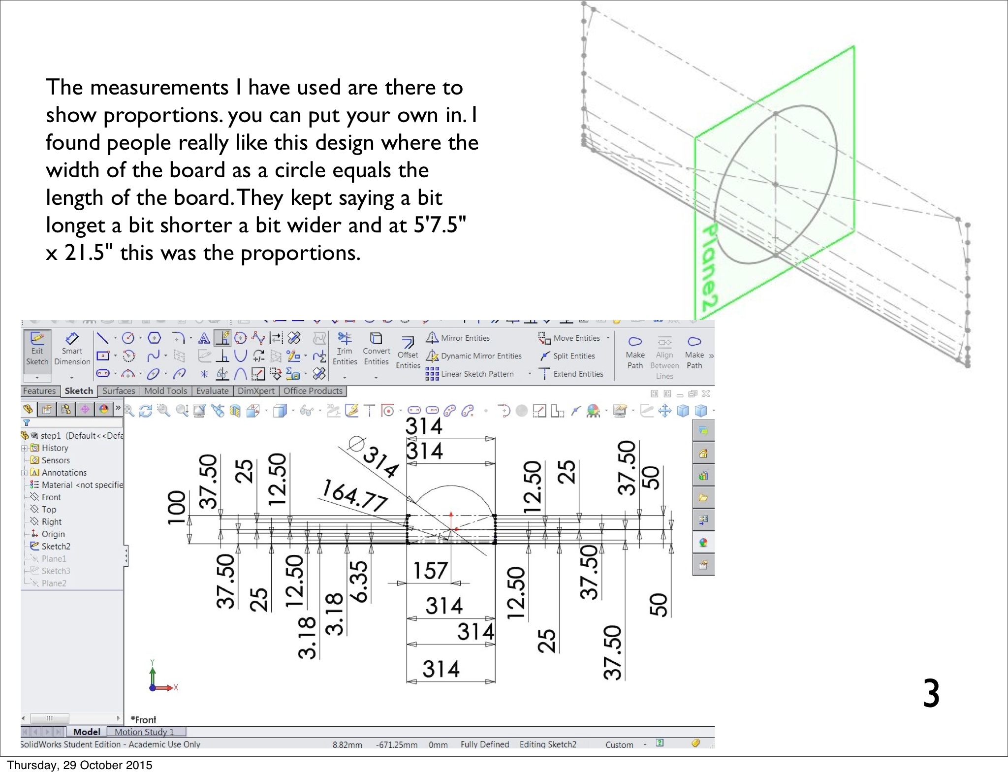
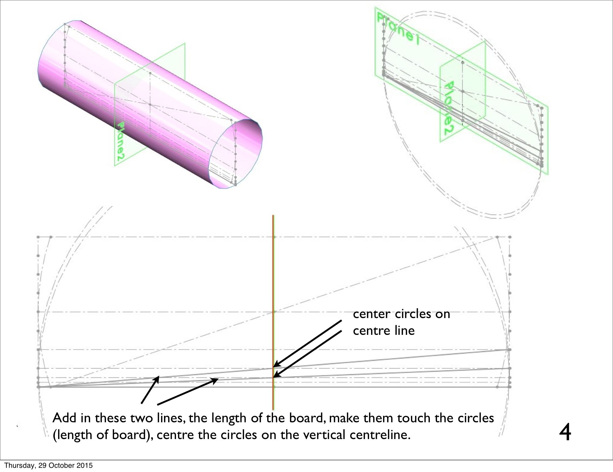
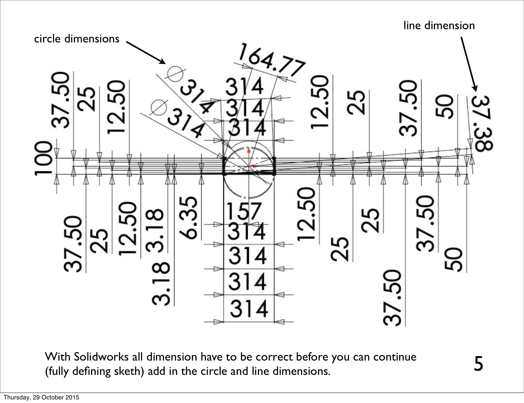
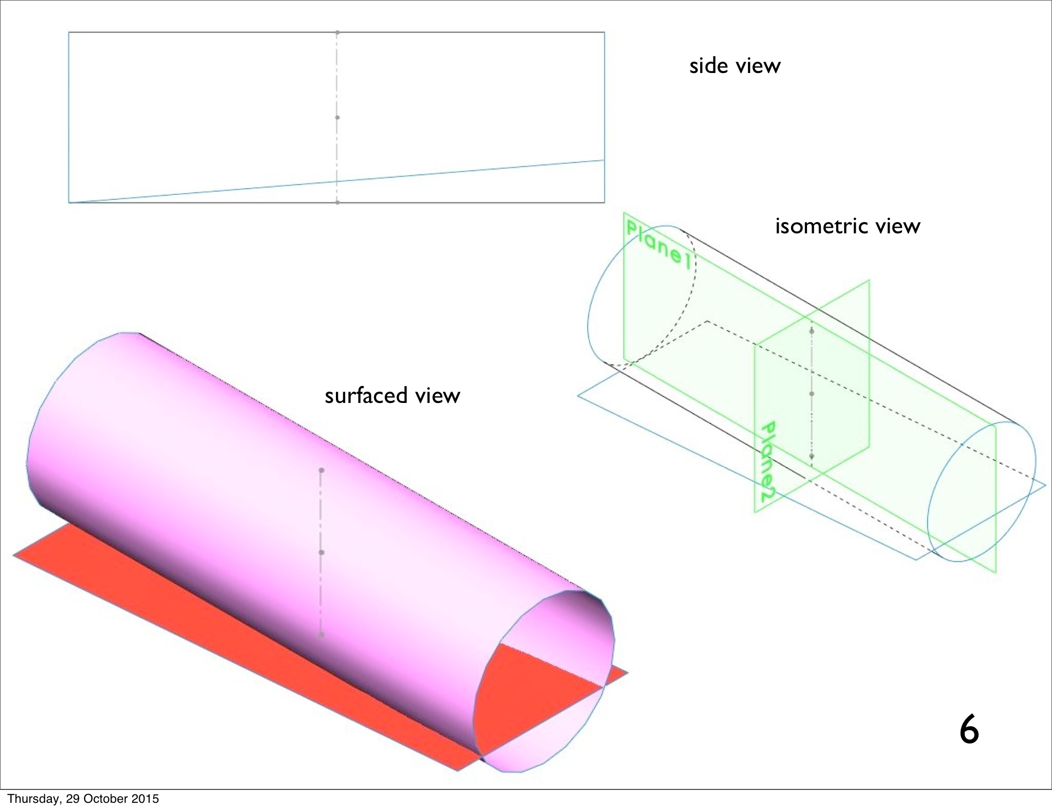
Following is the first section of a step by step process to designinga classic geometry surfboard. This first section is just to create a 3D outline, the complete process will create a whole board and fins with fin placement. I’ll try putting this first section out there and see what happens. I believe with this concept of “surfboard geometry” any board can be made, I’ve chosen this design because it is the most classic basic geometry and the board is popular. These steps are shown in Solidworks 3D engineering CAD. Solidworks is a big company, it’s CAD is one of the best in the world and there is a free student version (which this is) with complete tutorials and accreditation available to you. Solidworks.com
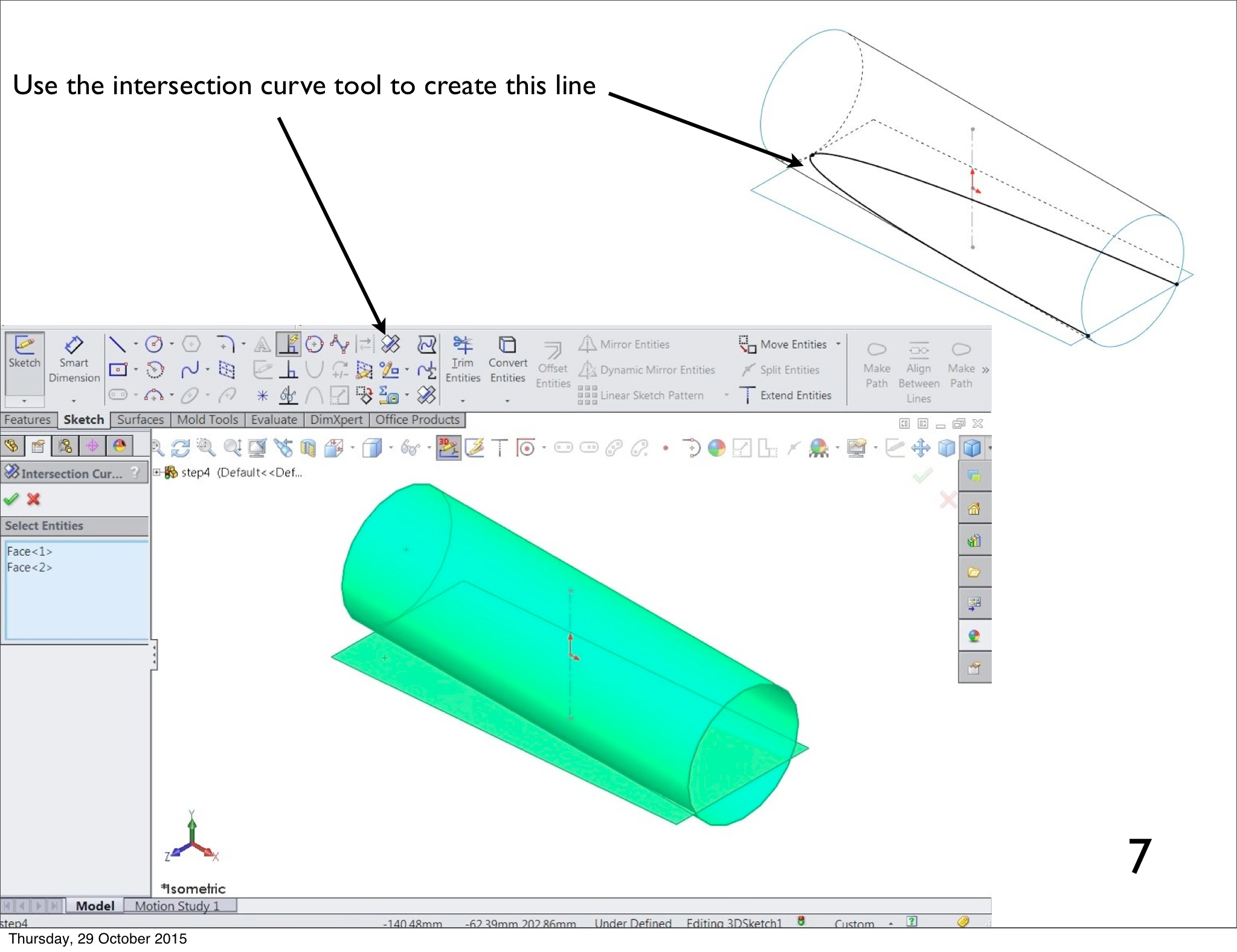
The following steps are the steps for any 3D CAD, if you get stuck on exactly how to do it in Solidworks, contact me and I will direct you. I might eventually put a detailed explanation up on my surfboardgeometry Blog. To do these steps in Solidworks you will need to go … options/customize/comands and drag the sketch tools of moving, rotating, copying and the interscetion curve tool. into your tools area. To use them make sure you click on what you want to move and delete the ‘relations’ that hold it there.
Once you understand the principals and the variations of this “surfboard geometry” it is a pretty amazing surfboard design tool. I’ve spent years working on this and these step are what it has evolved into.
I give you this process free on the condition that you don’t pretend its your work. No one else in the world is doing this stuff yet, my past posts on the internet prove my history. If you want to build a business using this type of process and promote it as “surfboard geometry” (or some other name depcting a new design process) then you need to work out a deal with me. I will be fully supportive and cost you next to nothing. This work is licensed under a Creative Commons Attribution-NonCommercial 4.0 International License.
If you just make a few and sell them as part of a typical surfboard business, I don’t mind. I don’t need to be involved or informed. I’m just concerned about the global image being stolen from me.