hi Stoneburner
I woke up the other day at about 4am with this concept for you to consider …
hi Hans
Great to come back and see what you have done. I like your question to Bill and with respect I will give Bill time to answer. Nice to see posts from you again Bill …
hi Wooddave
OMG, I nearly fell off my chair finding that. Can you take that intersection line and get Solidworks to respond to it? Do you know about the extrude cut tool, convert entities tool? Does it work with Lofts? (shows how much I know) lt’s a classic shape. I’m keen to see where it goes to next. You might just need to bend it too a rocker.
hi Lawless
Great to see you posting again, I am really keen to get boards cut on an APS3000, but I dont think AKU (is that the CAD your friend is using?) will read any other CAD files … Can you find out what file formats your friends APS3000 can read? yeah … I will send you what ever you request if I can.
Hans, if I had an interest in the thrust of your question, I’d answer it. But I don’t. When I want a line, or curve, I create it. My comments are intended to encourage surfboard building hopefuls to get their hands onto tools, and off their keyboards. I long ago understood that cones, cylinders, and thier sections, produced interesting lines, that might be applicable to surfboard design. I had little interest in engaging in intellectual posturing. Still don’t. If that sort of exercise excites you, then go for it. It is the hands on, creative process, that excites me. So that is the path I choose. And what I encourage others to do.
I haven’t noted any intellectual posturing here, just some math geeks (and I use that word with respect!) stoked on the application of geometry to surfboard design. I’m an old school draw it by hand and build it by hand guy myself, but I think its great that malaroo has pursued his vision, and shared it with others here on swaylocks. The thread title is very clear and self-evident, so there would be little reason for anyone not interested in surfboard geometry to even click on it, which I think was a great move on malaroo’s part. I know malaroo can and does build surfboards by hand, from a design in his head, and has posted pics of his craftsmanship. But I also know he’s a math whiz, and I think its awesome to see him and the other posters here working out the geometry of surfboard design on an open forum. Like I said, thats what swaylocks is here for. Carry on gentlemen!
Hi Malaroo glad you’re back.
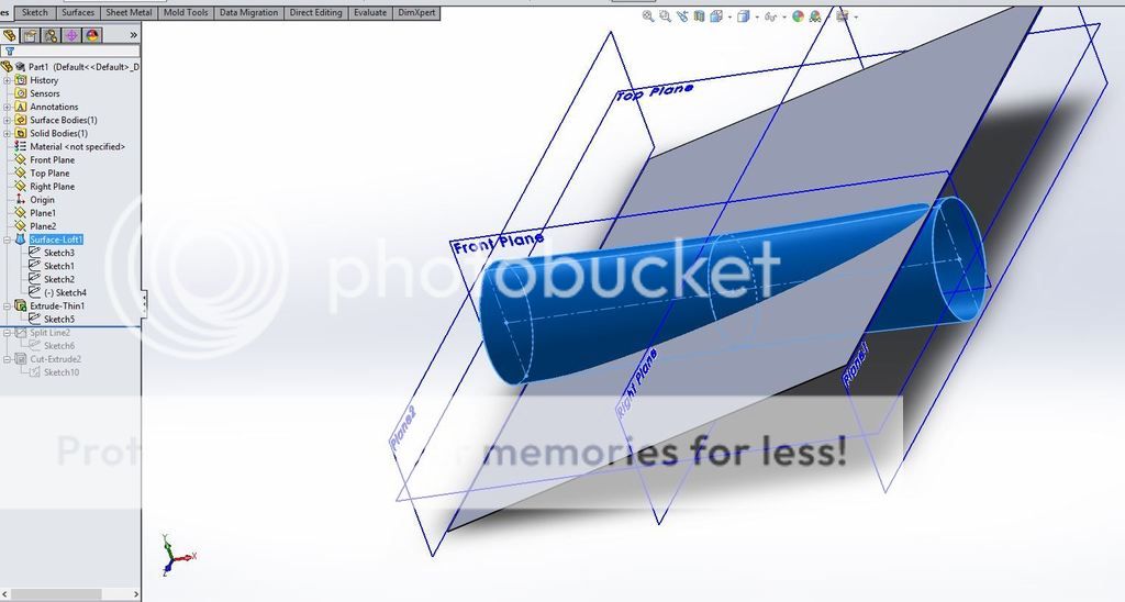
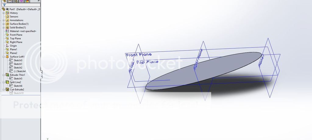
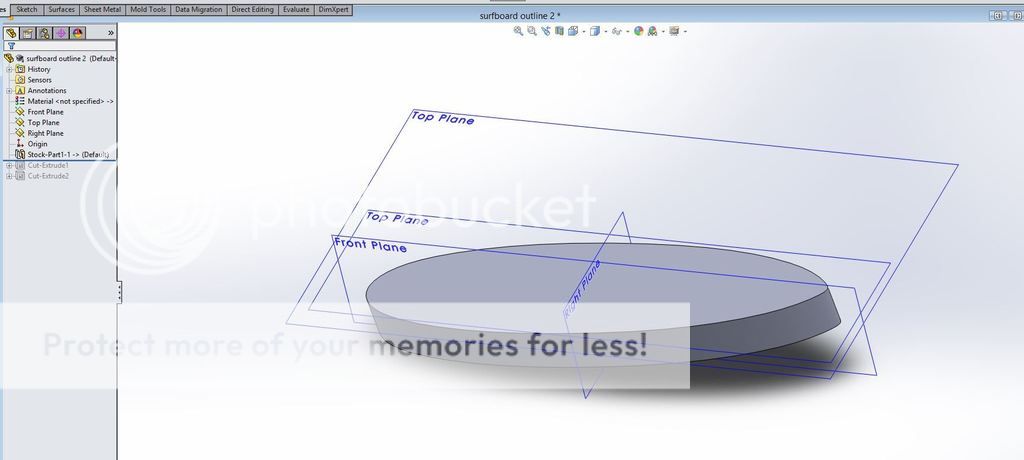
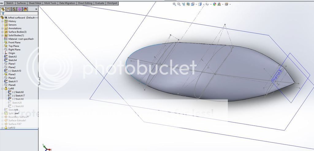
I’ve continued to mess around a little more and here’s what I’ve done
I used the first line to extrude a thin solid that runs through the cylinder.
Then I used intersection curves to create a sketch on that surface that followed the desired outline.
then I cut away the extra stuff
Then I extruded that out to create my “blank”
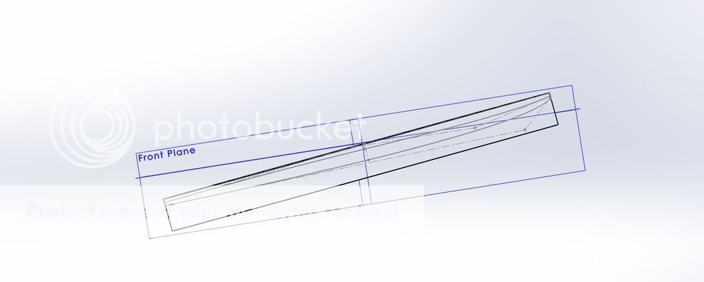
Then created a sketch (on the front plane) for the rocker and deck profile
Then did an extruded cut using that sketch
still pretty blocky, it will probably take a lot more sketches and lofted cut to produce a useable rail profile.
but really all of the geometry that a builder that is not planning on using a cnc is here and can be either printed full size on paper or used to take strategic measurements
Of course the rocker and deck profile are just quick approximations to demonstrate the method.
I don’t make any claims that this is a useable shape. but the beauty is that it can be changed with a few clicks.
I still haven’t learned to bend bodies or surfaces in solidworks so that might be for a different day.
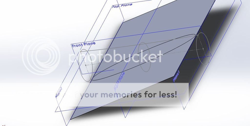
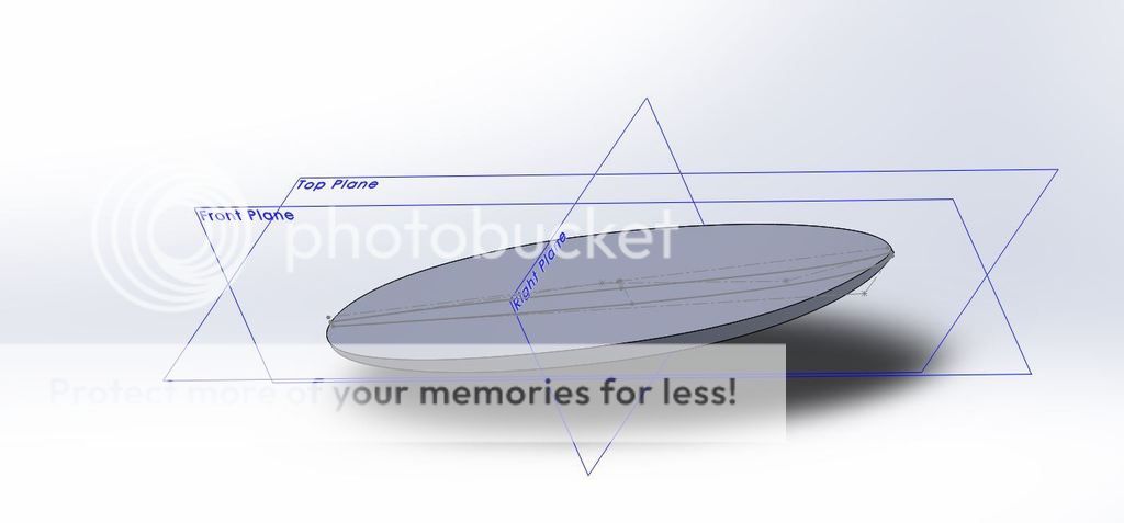
I have also been tooling around with using the loft method, it really has the most promise for designing a finished boardshape (rails and all).
(Full disclaimer this shape is total crap but I wanted to show what might be possible)
I’m sure there are others who can do a lot better at this than me.
Basically you use your rocker profile as a guide curve and use sketches at key points as profiles.
I really like using style splines to generate these shapes but it will take some more practice to get satsfactory results using them.
using this method you have a lot of control over bottom profile and deck dome as well.
Malaroo,
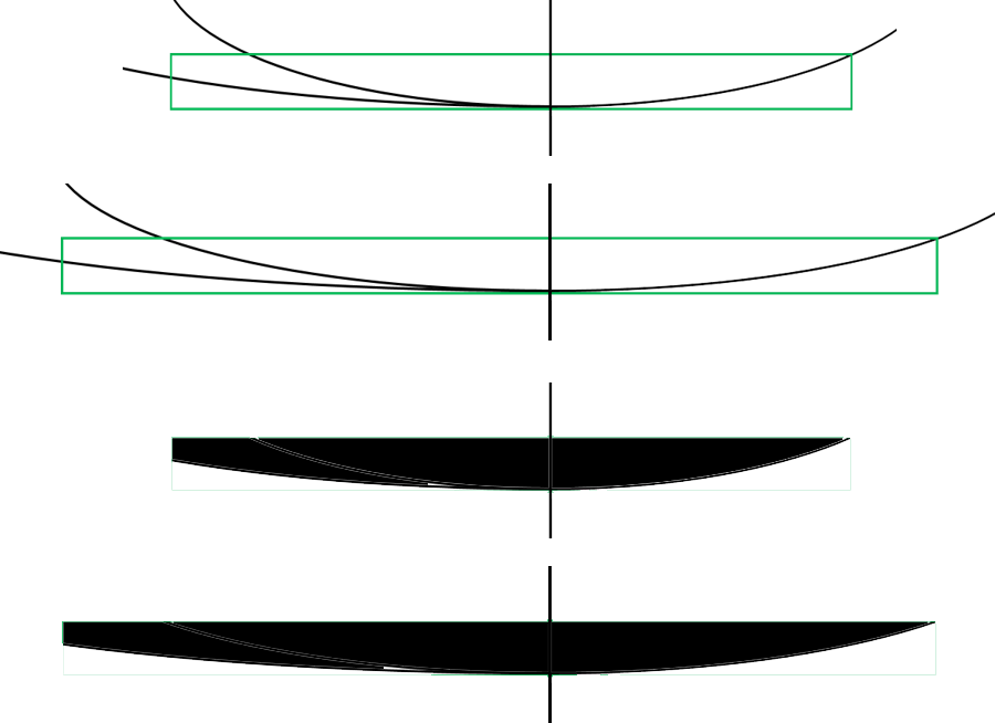
I liked your earlier perspective that rocker is/should be an extension of planshape. I have been playing with that idea and the green overlay box above. Create an overaly box with height equal to desired nose rocker height. Divide the box with a vertical line. The front and rear sections of that box are proportional to the front and rear sections (relative to the widepoint) of the planshape. Align the overlay box vertical line with the widepoint of the planshape. Stretch the box until the top of the box front corner intersects the front curve of the planshape (bottom of box is tangential to the curve apex). Group the curve with the overlay box as one image. Increase the box length (with curve) to planshape length – with aspect ratio unlocked. You now have a bottom rocker curve generated from the planshape, with the same asymmetry. Hard to describe with words. Graphics below:
Each image’s dimensions are not scaled to match one another proportionally. I will fix that later for a better before and after stretch comparison.
EDIT: Originally, I said align the overlay box with the “midpoint” of the planshape. That should have been align the box with “widepoint.”
Hi Stoneburner
With your picture above and your previous picture taking the rocker out of the planshape that is a very interesting and probably viable option. Any way of comparing that to a conventional rocker? I guess it doesn’t matter, the test is trying it and seeing if it works. Very interesting stuff!
Typing this quickly. Have to get at least one chore completed today…
Yes I can compare it to a rocker derived from stretching a more conventional planshape. I was going to use a stretched version of a retro fish for a planshape and rocker (5.5 ft to 7.5 feet). I abandoned the stretched retro fish when I started combining elipses of differing lengths at their midlines. I was planning on using the rocker from that stretched fish but slightly changed the location of the widepoint for the double ellipse.
I compared the tail and nose rocker heights from the stretched double ellipse planshape with that of the stretched retro fish. Tail rocker was very close to 2" for both and nose rocker was 4.4" for the stretched Double E planshape and about 4.7"(give or take 0.1 inch) for the stretched fish rocker. But these comparisons are from memory and a very quick check of dimensions.
I will have to do a bit of manipulating of original figures. But I may be able to generate images to compare both bottom rockers. Mind though that the planshapes are different now – assymetric double ellipse vs. stretched retro fish.
I am liking the planshape derived rocker concept…
Its great fun creating a concept
In the 60’s I used high school math to create elongated parabolic curves for templates .
Slicing a cylinder ,to me ,misses so much of what many of us have learned as to what makes boards work the way they do .
But please continue to enjoy your adventure and have fun .
Hey Greg - actually, “slicing a cylinder” seems like a gross oversimplification of the whole process here. And according to ride reports, malaroo’s boards work great. Maybe high school math is more your forte, =) anyway, hope you continue to have fun doing what you do.
I have been using programs for about 15 years now .
Its a blessing I handshaped for over 35 years before that , going thru each era of design change - a great learning experience .
Slicing a cylinder is an intentional simpilfication instead of addressing several points , such as best fins and placements for a design and how that is achieved .
I 've had a lot of fun seeing my help make other shapers great - good times . This can only happen thru disscussion .
Off to fix a bike tire :-)
That’s great, I’m happy for you, you should be proud. Stick around, he’ll probably eventually get to the fins part too. I know from our conversations that he has spent a lot of time working out the fins and placement for his boards.

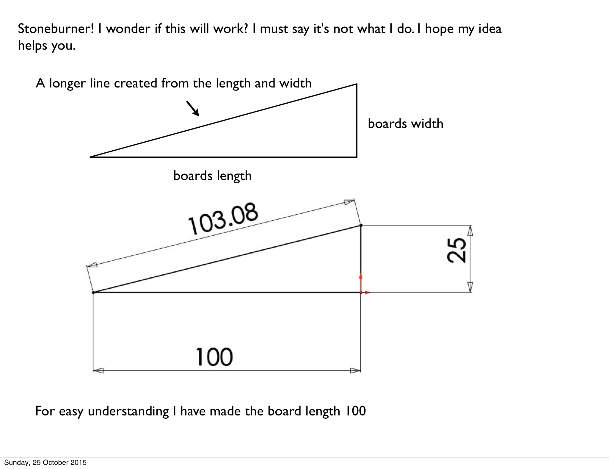
In the OpenSCAD files, the length of the diagonal is parameterized instead of the horizontal.
If you take alpa = left angle
alpha = asin (width / diagonal_length)
horizontal_length = cos (alpha) * diagonal_length
Not sure if this helps, but I hope it does.
I have a question about rocker in general. You guys have been drawing it as a single curve.
I was wondering does the rocker on most boards fit into that description ?
I only have a few boards in my quiver to go by, one of them seems to have a pretty continuous curve and another is quite flat through the middle… In my mind I envision rocker as being 3 separate stages of variable length and curvature blended together, the nose section having a lot of curve flowing into a flat(ish) midsection under where the riders weight is expected to be, flowing into a tail section that gently curves back upward. Throwing concave into the mix also adds literally a whole other dimension which makes things even harder to quantify.
Is it a mistake to break it down into sections that way ?
Hi Wooddave,
It is definately not a mistake, there is no right or wrong in this thread.
Malaroo is indeed using a continuous rocker. (projected ellipse)
How I see malaroo’s method, is as a method to reduce the shape complexity to a small set of parameters. So splitting to rocker increases the number of parameters.
However, there is nothing wrong with a larger set of parameters, it’s just more variables to control and play with.
Thanks for the explanation hans, yeah, I wasn’t sure if doing a continuous curve was customary or part of Malaroo’s method.
I tried a different approach. I created an overlay box the length of planshape and height of desired noserocker. This time I compressed and stretched the planshape instead to get a curve that fits the box rather than stretch the overlay box/curve section to planshape length. Curve fits the box: curve apex tangential to box bottom, front corner of box intersects the curve. The bottom rocker curve is/was very close to that of the stretched fish rocker. Difficult to communicate with words but it worked well. Bottom line, compress and stretch the planshape to get a curve that fits the box.