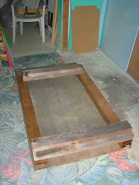
As I’ve discussed on the “show us your flex” thread, at Coil Construction we use a simple jig
to measure flex in different portions of the board. I’m offering up it’s design so that the builders
of flexible boards everywhere will have a means to compare their flex rates accurately. I’m
open to input on improvements, but we need to reach agreement on a design so that consistent,
repeatable data is obtained…
This is NOT an ASTM technique, rather it’s a simple, easy to make garage-style device. We can
go the high-end route if anyone wants to, but that requires submitting boards to a testing facility,
paying for the tests, etc.
Wish I could post pictures, but I’m still trying to figure that one out. That re-sizing thing has got me stumped.
This “jig” is so simple that pics aren’t really needed, anyway.
Start with a baseplate of plywood or heavy masonite about 4’ x 3’. Attach 4’’ x 4’’ beams on the long
sides, one on each edge, the same length as the base. Cut two more pieces of 4’‘x4’’ to span across
from beam to beam. Attach ONE of these securely at one end of the jig. The other one can be unsecured
as you will see. That’s it for the ‘‘building’’. If your boards flex a lot you may need to raise the crossmembers
to get more of a gap to the baseplate.
To measure flex in the center of the board, say the middle 3’ of a shorty, place the moveable crossmember
3’ from the fixed one, and set the board across them (like a rack) deck up. Place an ‘‘auto-stop’’ tape measure
on the base, extended to meet the bottom pre-load. Place the load in the center (we use 40-50 lb bags of
mortar) and the flex will push the extended tape down. Subtract the loaded measure from the pre-load and
you’ve got a measure of flex per whatever weight you chose.
To measure tail flex you don’t need the moveable crossmember. Slide the board (deck up) under the fixed crossmember
with the tail sticking out the end and most of the board resting on the baseplate. Pick your distance to be flexed
and locate the board so that the crossmember contacts the deck that distance up from the tailblock. (Some
distribution of load may be needed at this contact point.) Now you pull UP on the tailblock to flex the tail. The
attachment to apply this force can be as simple as a C-clamp and some shims or as complex as you want. To compare,
though, it needs to be a consistent point, say 1’’ up from the block. Find the starting point (your unflexed ""zero’')
and pick the distance you’re going to flex. A helper is kinda needed for this one, he measures while you pull up
on the tailblock. We use a fishing scale between the puller and the tail to measure the force needed to produce
a certain distance of flex.
The tail flex can be done two ways; one isolating the flex, one allowing the middle of the board to flex at the same
time. If you want to isolate the flex, secure everything forward of the crossmember to keep it from bending on the
fulcrum created by the crossmember. If you want to let the middle flex, only support at one point forward of the cross
(and this needs to be consistent for comparibility)
Now we’re open for discussion.
Mike


